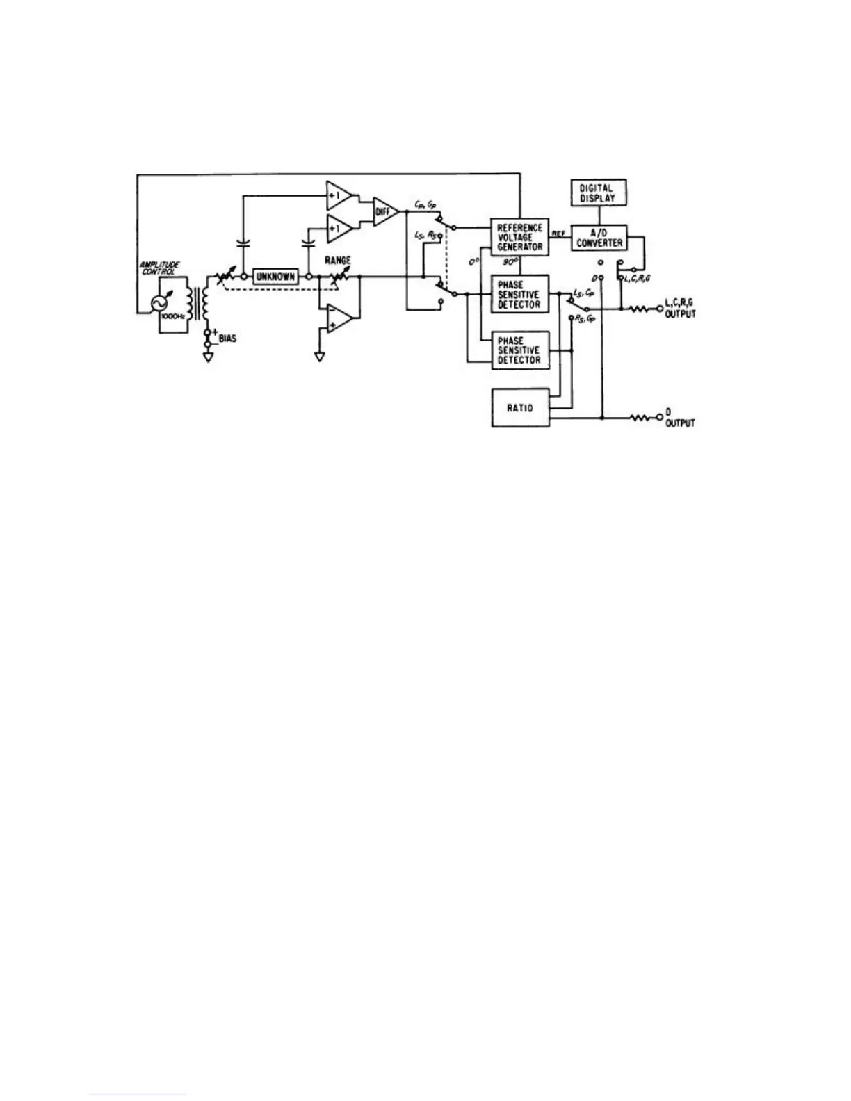
Figure 3-1. Model 252 Simplified Diagram
When measuring the dissipation factor (D) of inductors or capacitors, an analog ratio
circuit is used. This circuit compares the loss component (Rs or Gp) to the reactive
component (Ls or Cp) and presents a voltage proportional to D to the A/D Converter.
Analog output voltages are available at the rear of Model 252 for the selected function
(L, C, R or G) and simultaneous D (for L or C unknowns).
3-2