Specification-2225 Service
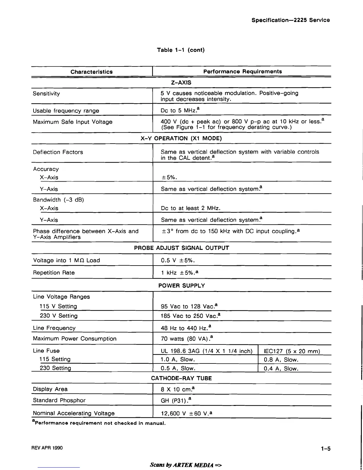
Table 1-1 (cont)
Characteristics
X-Y OPERATION
(XI MODE)
Performance Requirements
Sensitivity
Usable frequency range
Maximum Safe Input Voltage
Z-AXIS
5 V causes noticeable modulation. Positive-going
input decreases intensity.
DC
to 5
MHZP
400 V (dc
+
peak ac) or 800 V p-p ac at 10 kHz or less.a
(See Figure 1-1 for frequency derating curve.)
PROBE ADJUST SIGNAL OUTPUT
Deflection Factors
Accuracy
X- Axis
Y-Axis
Bandwidth (-3 dB)
X-Axis
Y-Axis
Phase difference between X-Axis and
Y-Axis Amplifiers
Same as vertical deflection system with variable controls
in the CAL
detent.a
+
5%.
Same as vertical deflection systema
Dc to at least 2 MHz.
Same as vertical deflection systema
+3O from dc to 150 kHz with
DC
input coup1ing.a
POWER SUPPLY
Voltage into 1 MR Load
Repetition Rate
0.5 V
+5%.
1 kHz -+5%.a
CATHODE-RAY TUBE
Line Voltage Ranges
1 15 V Setting
230 V Setting
Line Frequency
Maximum Power Consumption
Line Fuse
1 15 Setting
230 Setting
Nominal Accelerating Voltage
1
12,600
V
+60 V.a
a~erformance requirement not checked
in
manual.
95 Vac to 128 Vaca
185
Vac to 250 Vacaa
48 Hz to 440
HZ.~
70 watts (80 VA)
.a
Display Area
Standard Phosphor
REV
APR
1990
UL 198.6 3AG
(1
I4 X 1 1/4 inch)
1.0 A, Slow.
0.5 A, Slow.
8
X
10 cma
GH (P3 1
)
.a
IEC127 (5
x
20 mm)
0.8 A, Slow.
0.4 A, Slow.
 Loading...