Theory of Operation-2225 Service
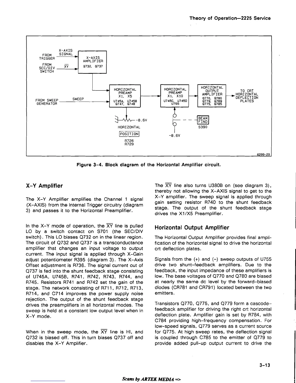
Figure
3-4.
Block diagram of the Horizontal Amplifier circuit.
X-AXIS
X-Y
Amplifier
FROM
SIGNAL
TRIGGER
*
-
FROM
SEC/DIV
XY
SWITCH
The X-Y Amplifier amplifies the Channel 1 signal
(X-AXIS) from the Internal Trigger circuitry (diagram
3) and passes it to the Horizontal Preamplifier.
X-AXIS
AMPLIFIER
0732. 0737
In the X-Y mode of operation, the
XY
line is pulled
LO by a switch contact on S701 (the
SECIDIV
switch). This LO biases Q732 on in the linear region.
The circuit of Q732 and Q737 is a transconductance
amplifier that changes an input voltage to output
current. The input signal is applied through X-Gain
adjust potentiometer R395 (diagram 3). The X-Axis
Offset adjustment is
R736. The signal current out of
Q737 is fed into the shunt feedback stage consisting
of
U745A, U7458, R741, R742, R743, R744, and
R745. Resistors R741 and R742 set the gain of the
stage. The network consisting of
R711, R712, R713,
R714, and C714 improves the power supply noise
rejection. The output of the shunt feedback stage
drives the preamplifiers in all horizontal modes. The
sweep is held at a constant low output level when in
X-Y mode.
When in the sweep mode, the
XY
line is HI, and
Q732 is biased off. This in turn biases Q737 off and
disables the X-Y Amplifier.
The
XY
line also turns U380B on (see diagram 3),
thereby not allowing the X-AXIS signal to get to the
X-Y amplifier. The sweep signal is applied through
gain setting resistor R740 to the shunt feedback
stage. The output of the shunt feedback stage
drives the
XI 1x5 Preamplifier.
FROM SWEEP
*
SWEEP
GENERATOR
Horizontal Output Amplifier
-8.6V
HORIZONTAL
I--%
piEq
-8.6V
R726
R729
6299-29
HORIZONTAL
PREAMP
U745C. U7450
U755
HORIZONTAL
PREAMP
XI. X5
U745A. U7458
0747. 0748
The Horizontal Output Amplifier provides final ampli-
fication of the horizontal signal to drive the horizontal
crt deflection plates.
I
Signals from the
(+)
and
(-)
sweep outputs of U755
drive two shunt-feedback amplifiers. Due to the
feedback, the input impedance of these amplifiers is
low. The base voltages of Q770 and Q780 are biased
at nearly the same dc level by the forward-biased
diodes
(CR781 and CR791) located between the two
emitters.
Transistors
Q770, Q775, and Q779 form a cascode-
feedback amplifier for driving the right crt horizontal
deflection plate. Amplifier gain is set by
R784, with
I
C784 providing high-frequency compensation. For
low-speed signals, Q779 serves as a current source
for
Q775. At high sweep rates, the deflection signal
is coupled through C785 to the emitter of Q779 to
provide added pull-up output current to drive the
TO CRT
-HORIZONTAL
DEFLECTION
PLATES
-
Scans
by
ARTEK
MEDIA
=>
HORIZONTAL
OUTPUT
AMPLIFIER
0770. 0780
0779. 0789
0775. 0785
 Loading...