Performance Check Procedure-2225 Service
Table
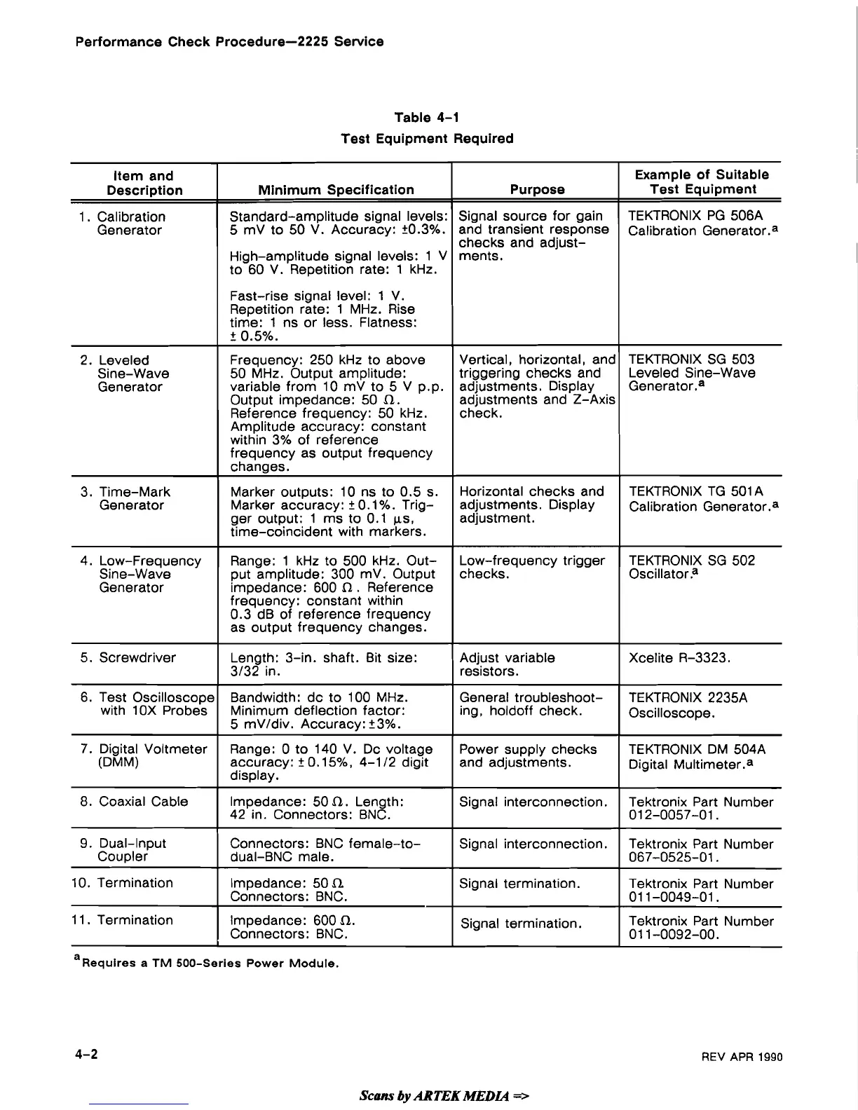
4-1
Test Equipment Required
a
Requires
a
TM 500-Series Power Module.
REV
APR
1990
Item and
Description
1
.
Calibration
Generator
2. Leveled
Sine-Wave
Generator
3. Time-Mark
Generator
4. Low-Frequency
Sine-Wave
Generator
5. Screwdriver
6. Test Oscilloscope
with 1
OX Probes
7.
Digital Voltmeter
(DMM)
8.
Coaxial Cable
9. Dual-Input
Coupler
10. Termination
11. Termination
Scam
by
ARTEK
MEDLQ
=>
Purpose
Signal source for gain
and transient response
checks and adjust-
ments.
Vertical, horizontal, and
triggering checks and
adjustments. Display
adjustments and
2-Axis
check.
Horizontal checks and
adjustments. Display
adjustment.
Low-frequency trigger
checks.
Adjust variable
resistors.
General troubleshoot-
ing,
holdoff check.
Power supply checks
and adjustments.
Signal interconnection.
Signal interconnection.
Signal termination.
Signal termination.
Minimum Specification
Standard-amplitude signal levels:
5
mV to 50 V. Accuracy: +0.3%.
High-amplitude signal levels: 1 V
to 60 V. Repetition rate: 1 kHz.
Fast-rise signal level: 1 V.
Repetition rate: 1 MHz. Rise
time: 1 ns or less. Flatness:
2
0.5%.
Frequency: 250 kHz to above
50 MHz. Output amplitude:
variable from 10
mV to 5 V pap.
Output impedance: 50
Q.
Reference frequency: 50 kHz.
Amplitude accuracy: constant
within 3% of reference
frequency as output frequency
changes.
Marker outputs: 10 ns to 0.5 s.
Marker accuracy:
2
0.1
%.
Trig-
ger output: 1 ms to 0.1
ps,
time-coincident with markers.
Range: 1 kHz to 500 kHz. Out-
put amplitude: 300
mV. Output
impedance: 600
Q
.
Reference
frequency: constant within
0.3 dB of reference frequency
as output frequency changes.
Length: 3-in. shaft. Bit size:
3/32 in.
Bandwidth: dc to 100
MHz.
Minimum deflection factor:
5
mV/div. Accuracy:
2
3%.
Range:
0 to 140 V. Dc voltage
accuracy:
2
0.15%, 4-1 12 digit
display.
Impedance: 50
Q.
Length:
42 in. Connectors: BNC.
Connectors: BNC
female-to-
dual-BNC male.
Impedance: 50
fi
Connectors: BNC.
Impedance: 600
Q.
Connectors: BNC.
Example of Suitable
Test Equipment
TEKTRONIX PG 506A
Calibration
Generat0r.a
TEKTRONIX SG 503
Leveled Sine-Wave
Generatorsa
TEKTRONIX TG 501A
Calibration Generat0r.a
TEKTRONIX SG 502
Oscillator?
Xcelite R-3323.
TEKTRONIX 2235A
Oscilloscope.
TEKTRONIX DM 504A
Digital
Mu1timeter.a
Tektronix Part Number
01 2-0057-01
.
Tektronix Part Number
067-0525-01.
Tektronix Part Number
01 1-0049-01.
Tektronix Part Number
01 1-0092-00.
 Loading...