Performance Check Procedure-2225 Service
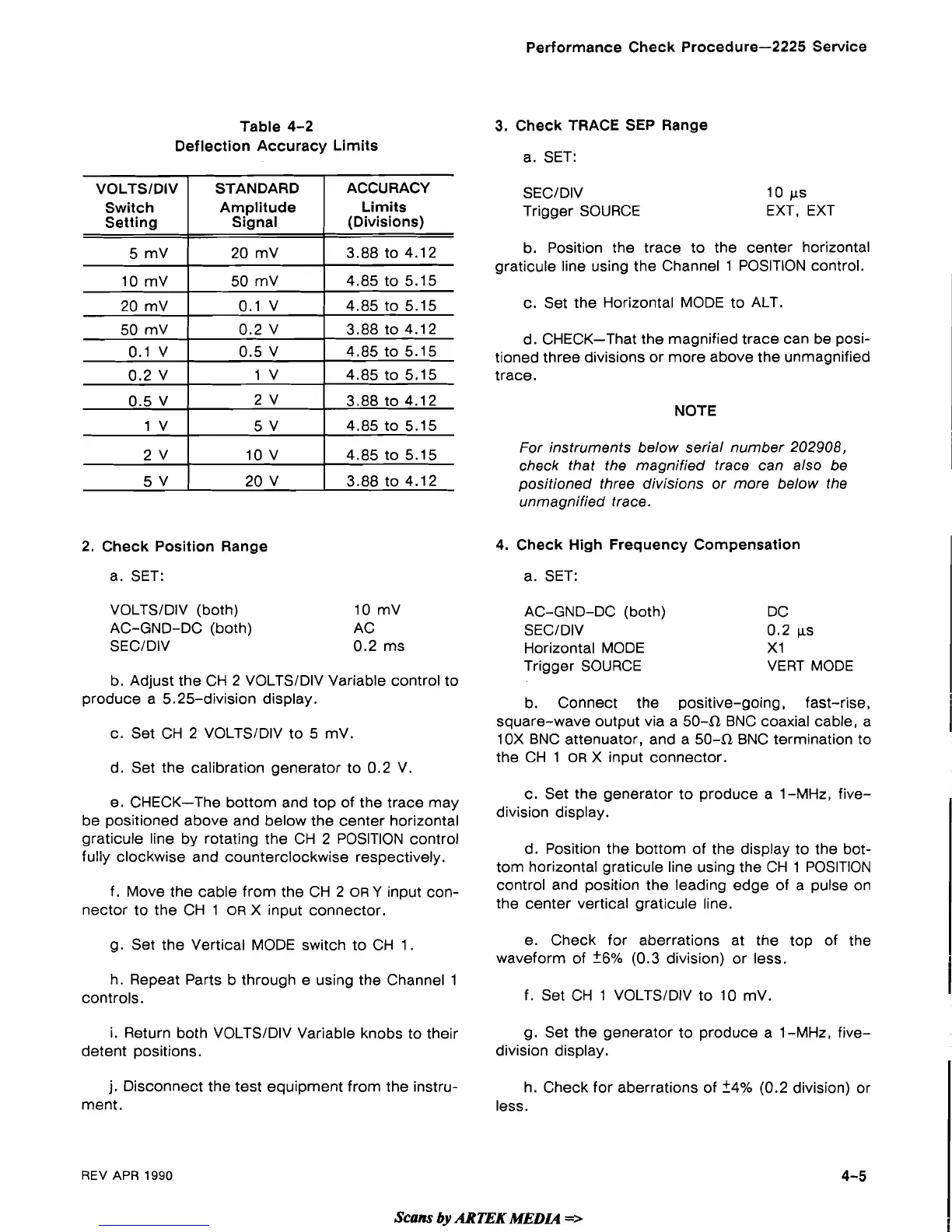
Table 4-2
Deflection Accuracy Limits
2. Check Position Range
a. SET:
ACCURACY
Limits
(Divisions)
3.88 to 4.12
4.85 to 5.15
4.85 to 5.15
3.88 to 4.12
4.85 to 5.15
4.85 to 5.15
3.88 to 4.12
4.85 to 5.15
4.85 to 5.15
3.88 to 4.12
VOLTSlDlV
Switch
Setting
5
mV
10 mV
20 mV
50 mV
0.1 V
0.2 V
0.5 V
1
V
2 V
5 V
VOLTSIDIV (both)
AC-GND-DC (both)
SECIDIV
STANDARD
Amplitude
Signal
20
mV
50 mV
0.1 V
0.2 V
0.5 V
1 V
2 V
5 V
10 V
20 V
b. Adjust the CH 2 VOLTSIDIV Variable control to
produce a 5.25-division display.
c. Set CH 2 VOLTSIDIV to
5
mV
d. Set the calibration generator to 0.2 V.
e. CHECK-The bottom and top of the trace may
be positioned above and below the center horizontal
graticule line by rotating the CH 2 POSITION control
fully clockwise and counterclockwise respectively.
f. Move the cable from the CH 2
OR
Y
input con-
nector to the CH 1
OR
X input connector.
g. Set the Vertical MODE switch to CH 1.
h. Repeat Parts b through e using the Channel 1
controls.
i.
Return both VOLTSIDIV Variable knobs to their
detent positions.
3.
Check TRACE SEP Range
a.
SET:
SECIDIV
Trigger SOURCE
10
FS
EXT, EXT
b. Position the trace to the center horizontal
graticule line using the Channel 1 POSITION control.
c. Set the Horizontal MODE to ALT.
d. CHECK-That the magnified trace can be posi-
tioned three divisions or more above the unmagnified
trace.
NOTE
For instruments below serial number
202908,
check that the magnified trace can also be
positioned three divisions or more below the
unmagnified trace.
4. Check High Frequency Compensation
a. SET:
AC-GND-DC (both) DC
SECIDIV
0.2
FS
Horizontal MODE
X1
Trigger SOURCE
VERT MODE
b. Connect the positive-going, fast-rise,
square-wave output via a 50-R BNC coaxial cable, a
10X BNC attenuator, and a 50-R BNC termination to
the CH 1
OR
X input connector.
c. Set the generator to produce a 1-MHz, five-
division display.
d. Position the bottom of the display to the bot-
tom horizontal graticule line using the CH 1 POSITION
control and position the leading edge of a pulse on
the center vertical graticule line.
e. Check for aberrations at the top of the
waveform of
26%
(0.3 division) or less.
f.
Set CH 1 VOLTSIDIV to 10 mV.
g. Set the generator to produce a 1-MHz, five-
division display.
j.
Disconnect the test equipment from the instru-
ment.
REV
APR
1990
Scans
by
ARTEK
MEDLQ
=>
 Loading...