Performance Check Procedure-2225 Service
TRIGGER
Equipment Required (See Table 4-1):
Leveled Sine-Wave Generator (Item 2) Dual-Input Coupler (Item
9)
Low-Frequency Sine-Wave Generator (Item 4) 50-CI BNC Termination (Item 10)
50-il BNC Coaxial Cable (Item
8)
600-CI BNC Termination (Item
11
)
INITIAL CONTROL SETTINGS
Vertical
POSITION (both) Midrange
MODE
CH 1
CH 1
VOLTSIDIV 0.1 V
CH 2
VOLTSIDIV
1
V
VOLTSIDIV Variable (both) CAL detent
Magnification (both)
Xl (CAL
knobs in)
AC-GND-DC (both) DC
Horizontal
POSITION (COARSE and FINE) Midrange
MODE
XI
SECIDIV 0.2 ~s
SECIDIV Variable CAL detent
MAG X5
Trigger
SLOPE
LEVEL
MODE
HOLDOFF
SOURCE
COUPLING
Positive
(I)
Midrange
P-P AUTO
MIN
VERT MODE
DC
PROCEDURE STEPS
1.
Check Trigger Sensitivity
a. Connect the leveled sine-wave generator out-
put via a
50-CI BNC coaxial cable and a 504 BNC
termination to the CH
1
OR
X
input connector.
b. Set the generator to produce a three-division
display at an output frequency of 5 MHz.
c. Set channel 1 VOLTSIDIV switch to
1
V
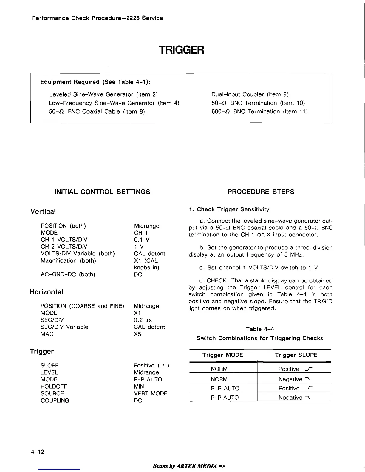
d.
CHECK-That a stable display can be obtained
by adjusting the Trigger LEVEL control for each
switch combination given in Table 4-4 in both
positive and negative slope. Ensure that the TRIG'D
light comes on when triggered.
Table 4-4
Switch Combinations for Triggering Checks
Scans
by
ARTEK
MEDL4
=>
Trigger MODE
NORM
NORM
P-P AUTO
P-P AUTO
Trigger SLOPE
Positive
f
Negative
7-
Positive
f
Negative
x
 Loading...