Adjustment Procedure-2225 Service
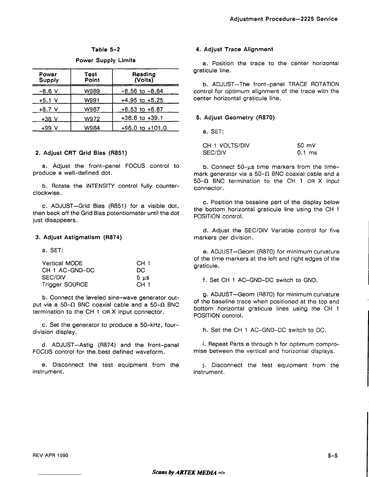
Table 5-2
Power Supply Limits
2.
Adjust CRT Grid Bias (R851)
Power
supply
-8.6 V
+5.1 V
+8.7 V
+38 V
+99 V
a. Adjust the front-panel FOCUS control to
produce a well-defined dot.
b. Rotate the INTENSITY control fully counter-
clockwise.
Test
Point
W989
W99 1
W987
W972
W984
c. ADJUST-Grid Bias
(R851) for a visible dot,
then back off the Grid Bias potentiometer until the dot
just disappears.
Reading
(Volts)
-8.56
to -8.64
+4.95 to +5.25
+8.53 to +8.87
+36.8 to +39.1
+96.0 to +101.0
3.
Adjust Astigmatism (R874)
a. SET:
Vertical MODE CH 1
CH 1 AC-GND-DC DC
SECIDIV 5
CLS
Trigger SOURCE CH 1
b. Connect the leveled sine-wave generator out-
put via a
50-52 BNC coaxial cable and a 50-52 BNC
termination to the CH
1
OR
X
input connector.
c. Set the generator to produce a 50-kHz,
four-
division display.
d. ADJUST-Astig
(R874) and the front-panel
FOCUS control for the best defined waveform.
e. Disconnect the test equipment from the
instrument.
4. Adjust Trace Alignment
a. Position the trace to the center horizontal
graticule line.
b. ADJUST-The front-panel TRACE ROTATION
control for optimum alignment of the trace with the
center horizontal graticule line.
5.
Adjust Geometry
(R870)
a. SET:
CH 1
VOLTSIDIV
SECIDIV
b. Connect
50-ps time markers from the time-
mark generator via a 50-52 BNC coaxial cable and a
504 BNC termination to the CH 1
OR
X
input
connector.
c. Position the baseline part of the display below
the bottom horizontal graticule line using the CH 1
POSITION control.
d.
Adjust the SECIDIV Variable control for five
markers per division.
e. ADJUST-Geom
(R870) for minimum curvature
of the time markers at the left and right edges of the
graticule.
f. Set CH
1
AC-GND-DC switch to GND.
1
g. ADJUST-Geom (R870) for minimum curvature
of
the baseline trace when positioned at the top and
bottom horizontal graticule lines using the CH 1
POS~T~ON control.
I
h. set the CH 1 AC-GND-DC switch to DC.
i. Repeat Parts e through h for optimum compro-
mise between the vertical and horizontal displays.
j.
Disconnect the test equipment from the
instrument.
REV
APR
1990
Scans
by
ARTEK
MEDL4
 Loading...