Adjustment Procedure-2225 Service
e. ADJUST-Trigger Sensitivity (R489) and Trigger
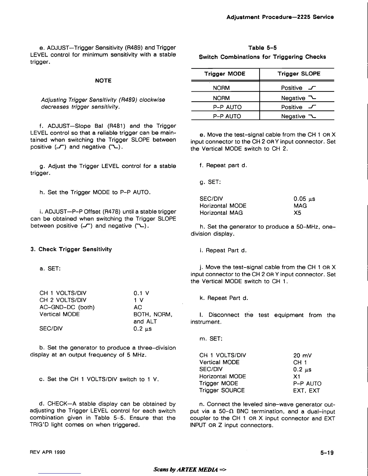
Table 5-5
LEVEL control for minimum sensitivity with a stable
Switch Combinations for Triggering Checks
trigger.
NOTE
Adjusting Trigger Sensitivity
(R489)
clockwise
decreases trigger sensitivity.
f. ADJUST-Slope Bal
(R481) and the Trigger
LEVEL control so that a reliable trigger can be
main-
e. Move the test-signal cable from the CH 1
OR
X
tained when switching the Trigger
SLOPE between
input connector to the CH 2 ORY input connector. Set
positive (1) and negative
(I).
the Vertical MODE switch to CH 2.
Trigger MODE
NORM
NORM
P-P AUTO
P-P AUTO
g. Adjust the Trigger LEVEL control for a stable
f. Repeat part d.
trigger.
g. SET:
Trigger SLOPE
Positive
1
Negative
Positive
1
Negative
I
h. Set the Trigger MODE to P-P AUTO.
SECIDIV 0.05 ps
Horizontal MODE MAG
i.
ADJUST-P-P Offset (R478) until a stable trigger
Horizontal MAG
X5
can be obtained when switching the Trigger SLOPE
between positive
(I)
and negative (I).
h. Set the generator to produce a 50-MHz,
one-
division display.
3.
Check Trigger Sensitivity
i. Repeat Part d.
a. SET:
CH 1 VOLTSIDIV
CH
2
VOLTSIDIV
AC-GND-DC (both)
Vertical MODE
SECIDIV
0.1
v
1
v
AC
BOTH, NORM,
and ALT
0.2
ps
b. Set the generator to produce a three-division
display at an output frequency of 5 MHz.
c. Set the CH 1 VOLTSIDIV switch to 1 V.
j.
Move the test-signal cable from the CH 1
OR
X
input connector to the CH 2
OR
Y input connector. Set
the Vertical MODE switch to CH 1.
k.
Repeat Part d.
I.
Disconnect the test equipment from the
instrument.
m.
SET:
CH 1 VOLTSIDIV
Vertical MODE
SECIDIV
Horizontal MODE
Trigger MODE
Trigger SOURCE
20 mV
CH 1
0.2
ps
XI
P-P AUTO
EXT, EXT
d. CHECK-A stable display can be obtained by
n. Connect the leveled sine-wave generator
out-
adjusting the Trigger LEVEL control for each switch
put via a
504 BNC termination, and a dual-input
combination given in Table
5-5. Ensure that the
coupler to the CH 1
OR
X input connector and EXT
TRIG'D light comes on when triggered.
INPUT
OR
Z input connectors.
REV
APR
1990
Scans
by
ARTEK
MEDIA
=>
 Loading...