Maintenance-2225 Service
significant digits, a multiplier, and a tolerance value.
Metal-film resistors have five stripes representing
three significant digits, a multiplier, and a tolerance
value.
CAPACITOR MARKINGS.
Capacitance values of
common disc capacitors and small electrolytics are
marked on the side of the capacitor body. White
ceramic capacitors are color coded in picofarads,
using a modified EIA code.
Dipped tantalum capacitors are color coded in
microfarads. The color dot indicates both the
positive lead and the voltage rating. Since these
capacitors are easily destroyed by reversed or
excessive voltage, be careful to observe the polarity
and voltage rating when replacing them.
DIODE
COLOR CODE.
The cathode end of each
glass-encased diode is indicated by either a stripe,
a series of stripes or a dot. For most diodes marked
with a series of stripes, the color combination of the
stripes identifies three digits of the Tektronix Part
Number, using the resistor color-code system. The
cathode and anode ends of a metal-encased diode
may be identified by the diode symbol marked on its
body.
Semiconductor Lead Configurations
Figure 9-2 in the Diagrams section shows the lead
configurations for semiconductor devices used in
the instrument. These lead configurations and case
styles are typical of those used at completion of the
instrument design. Vendor changes and per-
formance improvement changes may result in
changes of case styles or lead configurations. If the
device in question does not appear to match the
configuration shown in Figure 9-2, examine the
associated circuitry or consult the manufacturer's
data sheet.
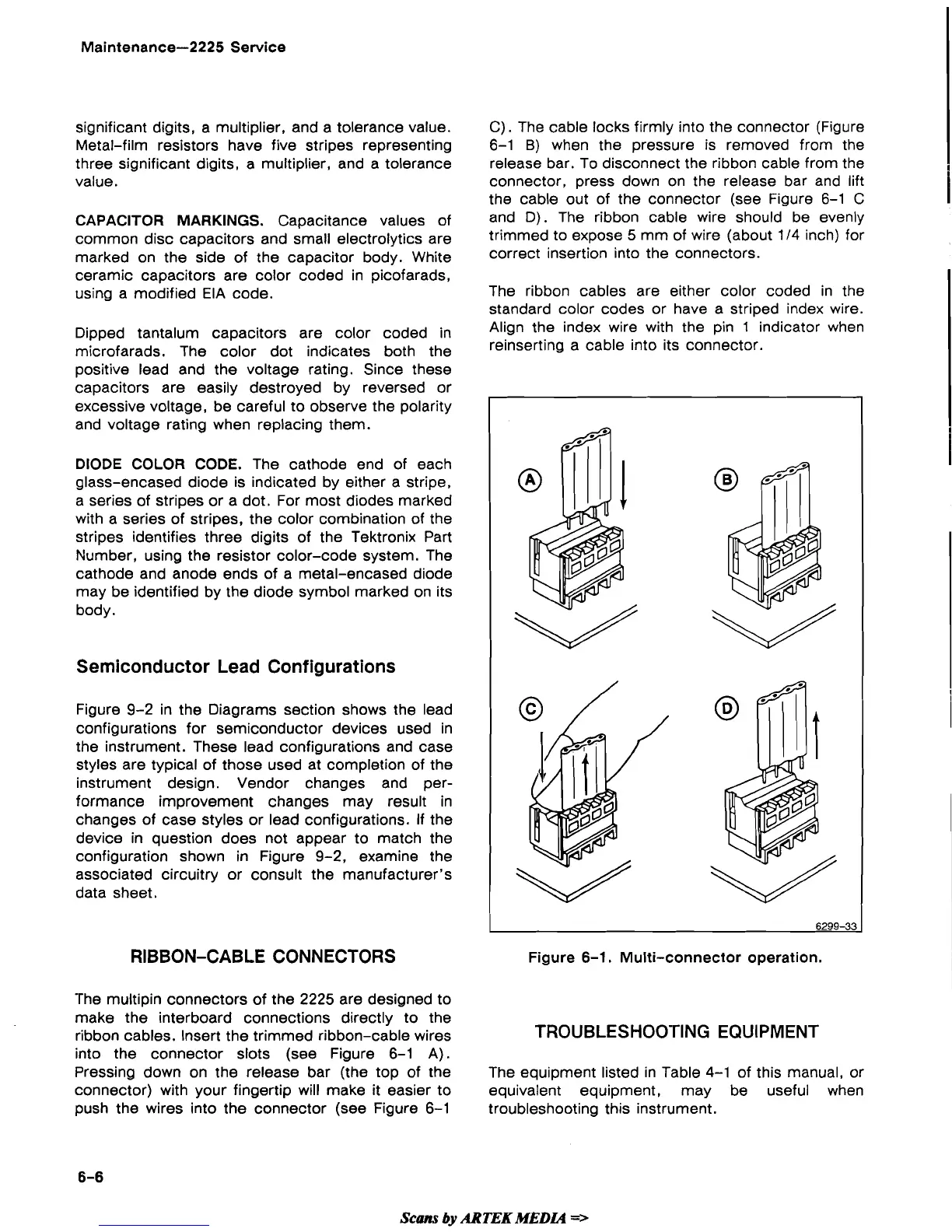
C).
The cable locks firmly into the connector (Figure
6-1
B)
when the pressure is removed from the
release bar. To disconnect the ribbon cable from the
connector, press down on the release bar and lift
the cable out of the connector (see Figure 6-1 C
and
D).
The ribbon cable wire should be evenly
trimmed to expose 5 mm of wire (about
114
inch) for
i
correct insertion into the connectors.
The ribbon cables are either color coded in the
standard color codes or have a striped index wire.
Align the index wire with the pin
1
indicator when
reinserting a cable into its connector.
RIBBON-CABLE CONNECTORS
Figure
6-1.
Multi-connector operation.
The multipin connectors of the 2225 are designed to
make the interboard connections directly to the
ribbon cables. Insert the trimmed ribbon-cable wires
TROUBLESHOO'rlNG EQUIPMENT
into the connector slots (see Figure 6-1 A).
Pressing down on the release bar (the top of the
The equipment listed in Table 4-1 of this manual, or
connector) with your fingertip will make it easier to equivalent equipment, may be useful when
push the wires into the connector (see Figure 6-1 troubleshooting this instrument.
Scans
by
ARTEK
MEDL4
=>
 Loading...