Maintenance-2225 Service
Voltage levels may be measured either with a DMM or
A defective component elsewhere in the instrument
with an oscilloscope. Voltage ripple amplitudes must can create the appearance of a power-supply
be measured using an oscilloscope. Before checking problem and may also affect the operation of other
power-supply circuitry, set the INTENSITY control to
circuits.
normal brightness, the
SECIDIV switch to 0.1 ms, the
Trigger MODE to
P-P
AUTO, and the Vertical MODE
7.
Check Circuit Board Interconnections.
switch to CH
1.
After the trouble has been isolated to a particular
circuit, again check for loose or broken connections,
When measuring ripple, use a
1X probe. The ripple
values listed are based on a system limited in
improperly seated semiconductors, and
heat-
bandwidth to 30 kHz. Using a system with wider
damaged components.
bandwidth will result in
higher readings.
8.
Check Voltages and Waveforms.
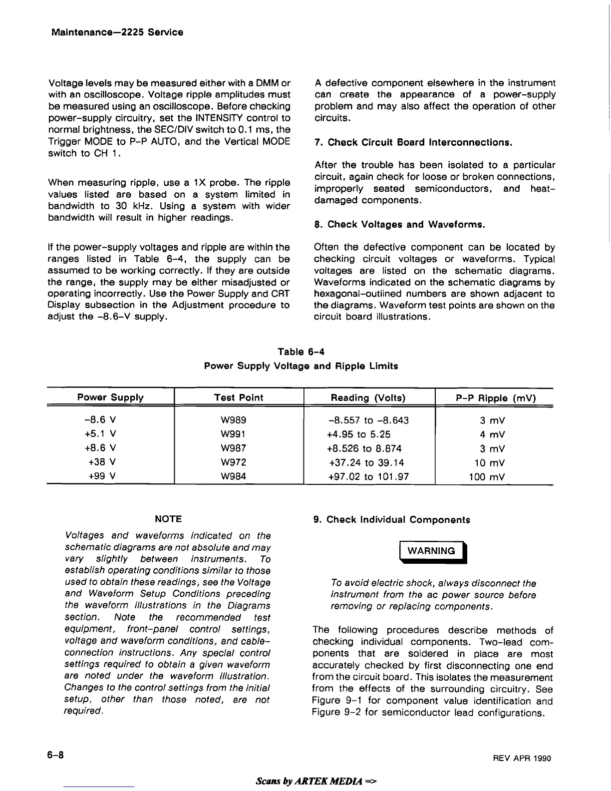
If the power-supply voltages and ripple are within the
Often the defective component can be located by
ranges listed in Table 6-4, the supply can be checking circuit voltages or waveforms. Typical
assumed to be working correctly. If they are outside voltages are listed on the schematic diagrams.
the range, the supply may be either misadjusted or Waveforms indicated on the schematic diagrams by
operating incorrectly. Use the Power Supply and CRT hexagonal-outlined numbers are shown adjacent to
Display subsection in the Adjustment procedure to the diagrams. Waveform test points are shown on the
adjust the -8.6-V supply. circuit board illustrations.
Table
6-4
Power Supply Voltage and Ripple Limits
NOTE
Power Supply
-8.6 V
+5.1 V
+8.6 V
+38 V
+99 V
Voltages and waveforms indicated on the
schematic diagrams are not absolute and may
vary slightly between instruments. To
establish operating conditions similar to those
used to obtain these readings, see the Voltage
and Waveform Setup Conditions preceding
the waveform illustrations in the Diagrams
section. Note the recommended test
equipment, front-panel control settings,
voltage and waveform conditions, and
cable-
connection instructions. Any special control
settings required to obtain a given waveform
are noted under the waveform illustration.
Changes to the control settings from the initial
setup, other than those noted, are not
required.
9.
Check Individual Components
Test Point
W989
W99 1
W987
W972
W984
WARNING
)
To avoid electric shock, always disconnect the
instrument from the ac power source before
removing or replacing components.
Reading (Volts)
-8.557
to -8.643
+4.95 to 5.25
+8.526 to 8.874
+37.24 to 39.14
+97.02 to 101.97
The following procedures describe methods of
checking individual components. Two-lead com-
ponents that are soldered in place are most
accurately checked by first disconnecting one end
from the circuit board. This isolates the measurement
from the effects of the surrounding circuitry. See
Figure 9-1 for component value identification and
Figure 9-2 for semiconductor lead configurations.
P-P Ripple
(mV)
3 mV
4
mV
3 mV
10 mV
100 mV
REV
APR
1990
Scam
by
ARTEK
MEDU
=>
 Loading...