BEFORE YOU BEGIN
QUICKSTART
CAPACITOR MOUNTING
INSTALLATION
SOLDERING
Brushless Wiring
3) CONNECT ESC TO MOTOR
First, determine the type of motor you are using. SENSORED
motors require the sensor harness, SENSORLESS motors do not.
Wire as shown in Fig. 6 and the chart below.
SPEED CONTROL BRUSHLESS MOTOR
(A) Red Wire (A) Red
(B) White/Blue Wire (B) White/Blue
(C) Black Wire (C) Black
SPEED CONTROL BRUSHED MOTOR
(-) Black Wire (-) Negative
(+) Red Wire (+) Positive
RADIO CALIBRATION, CONT...
Sensored/Sensorless Compatible
D2 Brushless Drive Technology
Brushed/Brushless Compatible
QuickTune Digital Setup
HotWire & Datalogging Capability
High Voltage Programmable BEC
RADIO CALIBRATION
SPECIFICATIONS
WIRING INSTRUCTIONS
Brushed Wiring
4.0 mm
High
power
Connector
Part #
TT3054
(3 Pairs)
FIGURE 4.
SOLDERING CONT...
1) CONNECT ESC TO RECEIVER
Plug the ESC into the throttle (TH) channel of the receiver.
Channel 1: Servo
Channel 2: ESC
“REMEMBER: 1 to Turn, 2 to Burn”
2) CONNECT ESC TO BATTERY
Visually verify that the connector on the battery pack and the ESC
match the chart below then connect.
DO NOT CONNECT BATTERY INCORRECTLY TO ESC,
VERIFY THAT THE BATTERY POSITIVE WIRE WILL
CONNECT TO THE ESC POSITIVE WIRE BEFORE
CONNECTING!
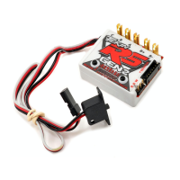
FACTORY RESET
TEKIN RS
INSTALLING THE
POWER CAP:
The capacitor should
be mounted directly to
the Battery Positive
BATT (+) and Battery
Negative BATT (-)
posts on the ESC, with
the capacitor wires
cut as short as possible.
The capacitor polarity is
indicated on the top of
the capacitor by a
colored half-circle
which is the BATT (-)
connection (Fig. 2).
CAUTION: A power capacitor is supplied with the RS Gen2
Series (TT3520) and MUST BE MOUNTED on the ESC for proper
operation (Fig. 1). Failure to use the power capacitor can cause
irreparable damage to the ESC.
FIGURE 2.
FIGURE 1.
POLARITY
INDICATOR
NEG (-).
Plan Speed Control Placement
1) Choose a location for the ESC that is protected from debris and
moving parts. Plan ahead with wire routing and try to keep the
motor leads about the same length. Motor leads should be short,
but not tight. Leave some slack in the wiring to account for chassis
flex and vibrations while driving.
2) Mock up your wire lengths for your planned ESC placement. It
is recommended to solder the power cap and all leads to the ESC
before mounting to the chassis.
3) Choose a wiring method for the motor and battery leads. Direct
wiring uses no plugs and provides the best connection between the
motor and the ESC. You can use Tekin 4.0mm Hi-Power bullet
connectors (TT3054, Fig 4.) for easy motor removal. Battery
connector choice is up to you, use the female plug on the battery
and the male on the ESC and double check the polarity.
4) To mount the ESC, clean the bottom with rubbing alcohol.
NEVER use any chemicals such as motor spray or acetone as they
will damage the plastic. Use the provided double sided tape or a
3M adhesive tape.
5) Secure the ON/OFF switch in a safe, accessible place away from
moving parts and debris.
Tips & Tricks
Placing the ESC in a vise (gently) provides a
stable work area to do a quality job ( Figure 3).
The order for proper
soldering is:
Tin Posts
Tin Wires
Heat Posts
Heat Wires
Heat both and connect
Hint: If the wire is too hot to hold 2” away from the solder joint, the
iron has been on for too long— stop, let everything cool and try
again. Excessive heat can damage the ESC.
Brushless wiring instructions refer to Fig. 6
Brushed, refer to Figs. 7 & 8 on reverse side.
FIGURE 3.
All Tekin ESCs have a built-in factory reset mode that resets all user
programmable settings to the default values. To activate, turn the
ESC on, then press/hold both the INCR and MODE buttons
simultaneously for 3-5 seconds. The LEDs will ramp up in sets of
three, confirming Factory Reset NOTE: Performing a Factory
Reset also resets all the radio calibration settings to their default
values. A radio calibration will need to be done.
Controls - RS Gen2/RS Spec Fwd/Brk or Fwd/Brk/Rev
Input (#Cells) RS Gen2/Spec 4-9 NiCd/NiMh (2-3S LiPo)
Motor Limits - RS Gen2
Brushless
Brushed Fwd Mode
Brushed Fwd/Rev Mode
8.5Turn, 36mm Can
10 Turn
12 Turn
Motor Limits - RS Spec
Brushless
Brushed Fwd Mode
Brushed Fwd/Rev Mode
13.5Turn, 36mm Can
20T Silver Can
20T Silver Can
Max Current
RS Gen2
RS Spec
120Amps
60Amps
Programmable BEC
RS Gen2
RS Spec
6-7.4V / 5.5Amp
6-7.4V / 3.7Amp
Dimensions
Weight
1.0 x 1.3 x 0.51 In. (25.4 x 33 x 12.9 mm)
2oz / 48g
WARNING: Exceeding product specifications or using equipment
outside of the specification ranges above automatically voids the
120-day manufacturer warranty. Any damage caused from misuse
or use of equipment outside of the specifications will be subject to
servicing and or replacement fees to be determined by the Tekin
Service Department. For further warranty information, please refer
to Section 26 or visit us on the web at www.teamtekin.com.
Hint: If the ESC fails to recognize your full throttle signal, try
reversing the throttle channel in the transmitter system menu.
STEP 1:
Power the
transmitter and
your ESC on.
STEP 2:
MODE
Press and
hold MODE for 3
seconds.
STEP 3:
STEP 5:
STEP 4:
Leave trigger centered
in Neutral.
WAIT FOR CHIME
Pull and hold full
throttle.
WAIT FOR CHIME
Push and hold full
brake.
WAIT FOR CHIME
LED BLINKING
CENTER
LED BLINKING
RIGHT
LED BLINKING
LEFT
NOTE: Before Radio Calibrating, ensure the ESC is hooked up
to the receiver in Channel 2 (CH2), a charged battery is properly
connected, and the transmitter is turned on and bound to your
receiver.
Refer to Section 10 below.
1) On your transmitter, set all trim adjustments to the middle,
throttle/brake EPAs and Dual Rate set to 100.
2) Press and hold MODE for 3-5 seconds or until the ESC gives a 4
chime confirmation. It is now in calibration mode and will start
by looking for the neutral signal first, while blinking the center
(#4) LED with a simultaneous “beep” with each blink.
3) Once neutral is found, the 4 chime confirmation will sound
again and the right (#7) LED will begin to blink, indicating the
ESC is looking for a full throttle signal. Pull and hold full throttle
until you hear the confirmation chime.
4) The ESC will then switch to the left (#1) LED and look for a
full brake/reverse signal. Push and hold full brake until you hear
the confirmation chime. After the confirmation, let go of the
trigger and the ESC will arm, go to neutral and actively show the
onboard temperature (Section 17).
Tekin’s QuickTune
PRESS MODE TO ACCESS:
LED1 - DRAG BRAKE
LED2 - BRAKE STRENGTH
LED3 - CURRENT LIMITER
LED4 - NEUTRAL WIDTH
LED5 - TIMING PROFILES
LED6 - MOTOR TYPE
LED7 - VOLTAGE CUTOFF
PRESS INCR TO:
Adjust the feature current-
ly selected. Refer to the
QuickTune adjustments
table below (section 13)
for ranges of adjustment
and what they accom-
FIGURE 5.
MODE RANGE DEFAULT
DRAG BRAKE (DB) 1-13 1 (No Drag)
BRAKE/REVERSE STRENGTH
(BS) —Brushlesss Mode Only
PUSH CONTROL ANTI DRAG
(PC)—Brushed Mode Only
1-13
1-13
4&5
1 (Off)
CURRENT LIMITER (LM) 1-13 13 (No Limiter)
NEUTRAL WIDTH (NW) 1-13 4&5
TIMING PROFILE (TP) 1-7 1 (Spec Blinky)
MOTOR TYPE (MT) 1-6 3 (Brushless)
VOLTAGE CUTOFF (VC) 1-4 2 (6.4V)
LED1: DRAG BRAKE provides immediate braking
action in neutral. This gently slows the car down when you let
off the trigger. Higher values increase the degree of drag brak-
ing.
LED2 (BRUSHLESS MODE): REV/BRAKE
STRENGTH adjusts your maximum brake strength
and reverse speed when in brushless mode. Higher values in-
crease brake strength and increase reverse speed.
LED2 (BRUSHED MODE): PUSH CONTROL or ANTI-DRAG
overcomes the natural drag of a brushed motor when throttle
returns to neutral. Low values give you a short duration push,
higher values a longer duration push.
LED3: CURRENT LIMITER adjusts the initial power
delivered to the motor under acceleration. Low val-
ues will decrease the initial power and give a softer feel to the
throttle. The highest value (13) gives full power to the motor, no
limiter is in effect. Ex: Current Limiter at 80 gives 80% power.
LED4: NEUTRAL WIDTH adjusts the dead band
around neutral. A low neutral width value will pro-
vide more precise and quick trigger sensitivity around neutral.
Higher values decrease trigger sensitivity.
LED5: TIMING PROFILES are pre-programmed with
5 preset profiles and 2 Custom profiles. Setting 1-5
will put the speed control in Sensored Only mode and apply the
preset amount of timing.
TP1: Spec Stock "blinky mode" 0*timing boost
TP2: 15* Timing Boost / RPM Range 5443-20,016
TP3: 25* Timing Boost / RPM Range 5443-20,016
TP4: 35* Timing Boost / RPM Range 5443-20,016
TP5: 45* Timing Boost / RPM Range 5443-20,016
*RPM Ranges are divided in half when running in 1S LiPo Mode*
After properly installing your ESC, follow these steps for a quick
setup:
1) With the ESC installed and properly wired, (Figs. 6, 7 & 8)
connect the battery.
2) Turn the transmitter on FIRST, then the ESC.
3) Take note any codes that may be present. Refer to Section 18 on
reverse side for codes.
4) Set transmitter throttle trims to 0 and throttle EPAs to 100. You
can access these features in the system menu on the transmitter.
5) Perform a Radio Calibration, refer to Sections 9 & 10.
6) Factory default voltage cutoff is set for a 2S LiPo battery @
6.4V. Double check the battery you are using and adjust Voltage
Cutoff if needed.
Read through this manual and familiarize yourself with the terms,
error codes and general workings of the ESC. Keep this manual for
future reference.
1) The RS Gen2 is intended only for 1/10th scale and smaller
vehicles that weigh under 5lbs ready to run.
2) Make sure the motor/battery are within recommended specs.
3) Check battery polarity; no reverse polarity protection.
4) Check polarity and labeling of solder posts before soldering.
5) Locate the power capacitor and note that it MUST be installed or
warranty will be void.
6) Use in or around water can damage the ESC and void the
warranty.
Congratulations and thank you for purchasing the RS Gen2
Brushless/Brushed Sensored Electronic Speed Control (ESC).
Carrying on the Tekin tradition of providing high performance,
top quality electronics, the RS Gen2 sets a new benchmark in
precision racing equipment. Based on the award-winning, inter-
nationally popular RS series speed control, the Gen2 brings
next level performance to your race machine.
ATTACHING WIRES TO THE ESC:
1) RED is used for battery positive (+BATT) and “A” Phase of the
motor. BLACK is for battery negative (-BATT) and “C” Phase.
White is for “B” Phase.
2) Tin all the solder posts on the ESC. Apply solder to the iron tip,
press it to the top of the post and feed more solder to fill the cradle
in the post. This process should take no longer than 2-3 seconds
repeat for remaining posts.
3) To tin the wires, strip the insulation back 3/32”- 1/8” and touch
the iron tip to the exposed strands. Feed solder to the wire until it
is evenly coated. 2-3 seconds again.
4) Attach the tinned wire to the tinned ESC post by heating both,
bringing them together and heating again (Section 5). The solder
should flow in 2-3 seconds. If you have trouble, clean and tin the
solder tip and retry once the pieces have cooled.
ATTACHING WIRES TO THE MOTOR:
1) Be sure to connect your motor to your ESC with the proper
wiring order: A – A, B – B, C – C.
2) Using the same techniques described above, solder the wires to
your motor.