Kona Micro User Guide T0005281_UG Version 1.2
TEKTELIC Communications Inc. Confidential Page 11 of 29
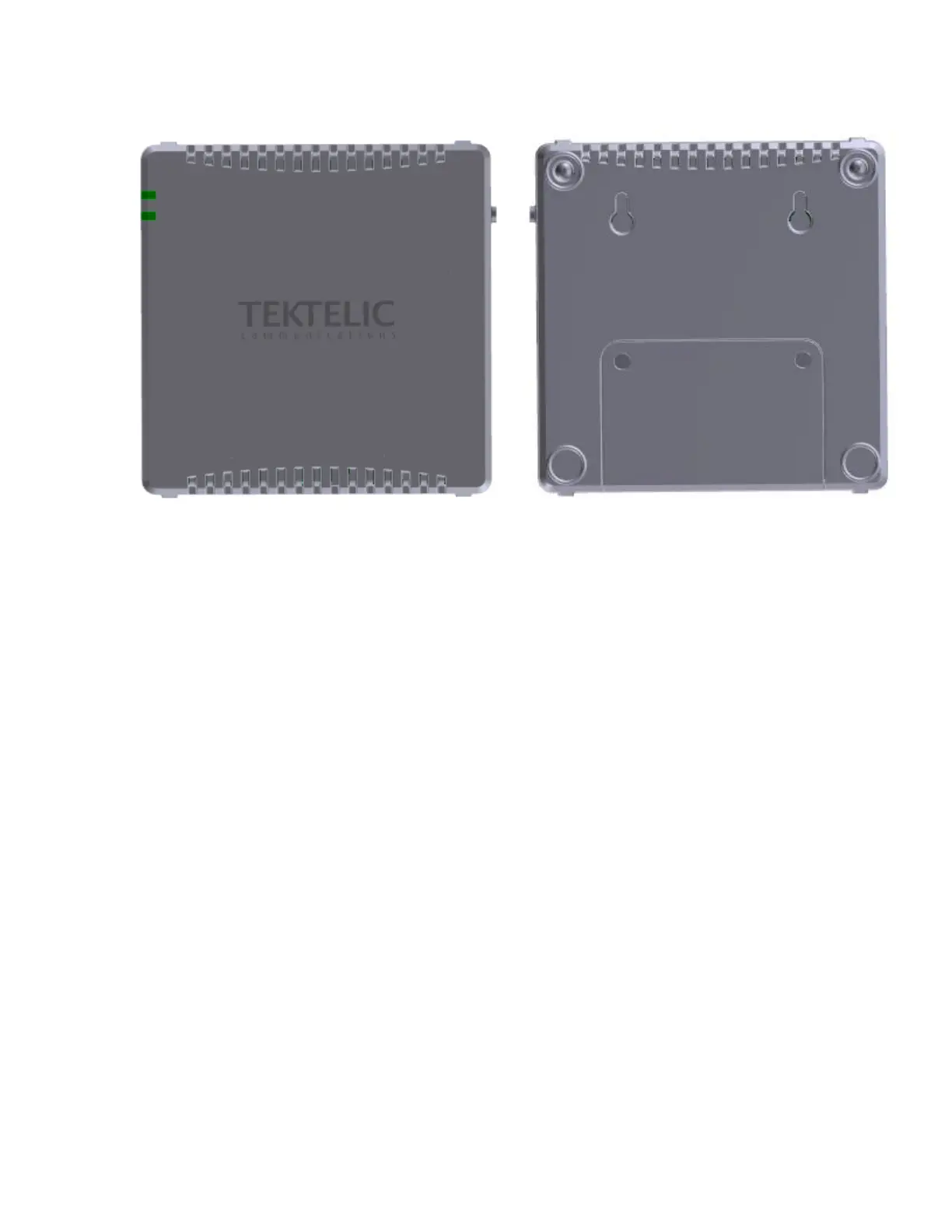
Figure 4: Kona Micro Gateway Module Wall Mounting Orientation
Ensure that the wall on which the Gateway is being mounted is secure, flat and able to support a
load of at least 0.5 kg (1.1 lbs).
The Kona Micro Gateway wall mounting procedure is as follows:
1. Install the M3 screws into the wall.
2. Install 2 site supplied M3 screws into the wall at 60 mm (2.4”) center spacing, leaving the
screw heads protruding with a 3 mm gap from the wall surface.
3. Hang the Kona Micro Gateway by mounting the two to keyhole slots onto the screws.
2.4. DC Power Cable Installation
The Kona Micro Gateway is powered from the supplied AC-DC power adaptor. The adaptor
provides 12 VDC with positive inner tip as shown below in Figure 5. The connector tip is a
standard DC Barrel connector-straight plug with 2.1 mm (inner), 5.5 mm (outer) diameters.
 Loading...