GB
48
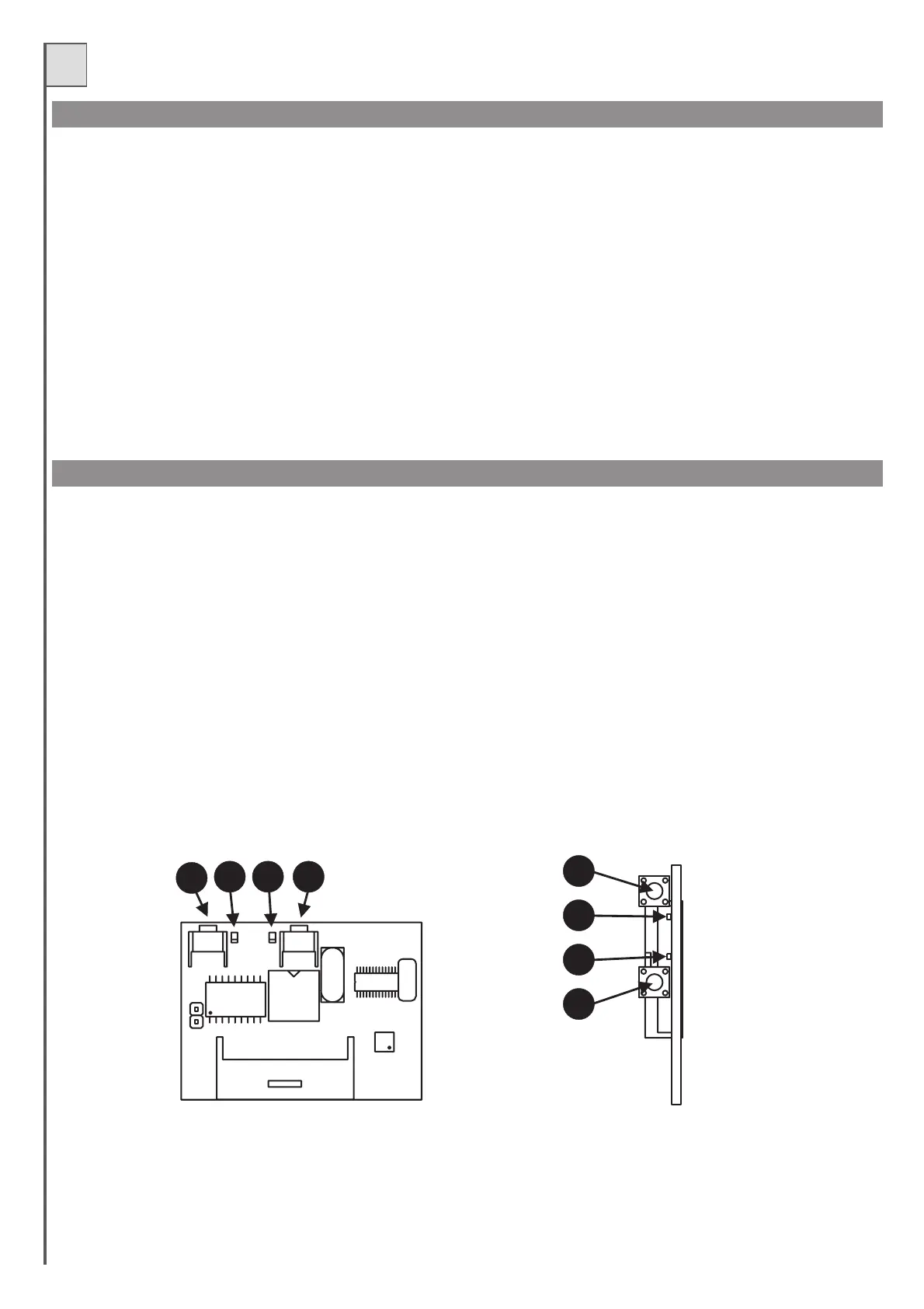
Led2
Led1
P1
P2
Led2
Led1
P1
P2
PHOTO TEST
MEMORY
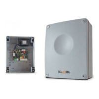
COUPLING TYPE RECEIVER model OC (optional)
To ensure correct operation of the phototest function, the system must be equipped with two power lines for the photocells; the first connected to
terminals 1 and 2 (powering the receivers) and the second to terminals 3 and 4 powering the transmitters (the phototest must be enabled with dip-switch
no. 7 set to ON).
The control unit checks efficiencyofthe photocells by simulating activationat the startof each manoeuvre.
If all functions correctly, the motors are activated and the manoeuvre starts; if the receiver malfunctions, the cycle is stopped and a series of fast flashes
are emitted on the gate open indicator and ledLD3.
The phototest function, as well as the obvious safetyfactor,offersthefollowing advantages:
- energy saving (the transmitters ofthe photocells areoffwhenthe gate isclosed)
- increased autonomy in the case of battery operation
- less wear of the photocell transmitter components.
The receivers are “self-learn” type and can memorise severalcodes on the same channel.
The functions of the two radio channels are:
Channel 1 Step/step
Channel 2 Pedestrian
Tomemorisethe transmitters proceedas follows:
- Insert the receiver in the connector (detail 23offig. 1)
- Power up the control unit and wait for the receiver ledsto turn off.
- On the receiver,briefly press thepushbutton of thechannel to be memorised, (P1 step/step orP2 pedestrian) andthe corresponding ledstarts to flash.
If the led emits double flashes, wait briefly andrepeat the operation (the pushbutton must only be pressed once).
-Transmitter with remote control to be programmed.
- If the led on the receiver emits alonger flash, thismeans thatmemorisation is successful.
- If the code is already present in thememory, the receiver leds all flash simultaneously.
The code memory can be reset if required, bypressing and holding P1 onthe receiver for approx. 15 seconds until allleds light up.
The aerial must be connected to terminals 42 (sheath)and 43 (control unit), see fig. 2.
-The phototest also works with photocell 3 (Jolly input).
- The control unit recognises and memorises (during time interval programming) which and how many photocells have been connected for
thephototest.
- On systems with the phototest function, when the gate is closed the photocell transmitters are not powered and the inputs are open (leds
off).
-To test the photocells when the gate is closed, short thetwo “Test” terminals (detail 11of fig.1) on the control unit.
-The photocells with connections for the phototest function only work during the manoeuvre.
-For further information and specifications, see the manual supplied with the receiver.