SIGNAL
1 RAIN SENSOR (YELLOW, GND)
2 RAIN SENSOR (BLUE, signal)
3 RAIN SENSOR (WHITE,12V)
4 WIND SENSOR (BLUE)
5 WIND SENSOR (BROWN)
6 LED OUTPUT (-)
7 LED OUTPUT (+24Vdc - max. 70W)
8 GND WIRED INPUT
9 CLOSE INPUT
10 OPEN INPUT
11 GND AERIAL
12 RF AERIAL
DIP1 DIP2 WIND SPEED (Km/h)
OFF OFF 40
OFF ON 50
ON OFF 60
ON ON 70
Only for “S” version
AERIAL
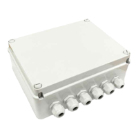
230Vac
Power
supply
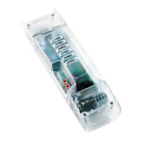
Dip switch
P1
Prog. button
230Vac
MOTOR
L1 L2 L3
L1: Rain alarm (ON)
L2: wind alarm (ashing)
L3: Not used
TRANSFORMER
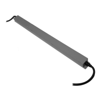
Rain Sensor
Wind Sensor
Wired input
LED OUTPUT
SIGNAL
15 MOTOR OPEN
16 MOTOR CLOSE
17 MOTOR COMMON
18 NEUTRAL 230Vac
19 LINE 230Vac
20 EARTH CONNECTION
OFF Application = Pergola
ON Application = Awning
3
1. Wiring and adjustments
The control unit can be used for both pergola (louvre) and sun awning applications.
Choose the desired functioning mode by means of DIP4:
In case of pergola application it’s necessary to congure the working time with procedure 6 (pag.7)
FUNCTIONING MODES: PERGOLA OR AWNING
 Loading...