This document provides service information for the Telefunken Bayreuth 5652 MX and Opus Studio 5650 MX, which appear to be high-fidelity audio receivers or tuners, likely from the mid-1960s given the component types. The manual details technical specifications, alignment procedures, and circuit modifications, indicating a sophisticated device for its era.
Function Description:
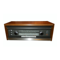
The Telefunken Bayreuth 5652 MX and Opus Studio 5650 MX are designed as comprehensive audio receivers, capable of receiving various radio bands and serving as a central hub for other audio components. They feature both AM (Amplitude Modulation) and FM (Frequency Modulation) radio reception, including shortwave bands, and are equipped with a stereo decoder for FM stereo broadcasts. The device incorporates a powerful audio output stage, suggesting it's an integrated amplifier-receiver, capable of driving external loudspeakers. It provides connections for a record player (stereo or monaural), a tape recorder (stereo or monaural), and external loudspeakers, making it a versatile component for a home audio system. The presence of an Automatic Frequency Control (AFC) system for FM tuning indicates a focus on stable and clear reception.
Important Technical Specifications:
- Power Supply: Operates on alternating current (AC) at 50/60 Hz, compatible with 117 and 230 volts.
- Power Consumption: Approximately 130 watts.
- Fuses:
- Mains fuses: 1.6 amp for 117 volts, 0.8 amp for 230 volts.
- Power output stages: 2 x 1.25 amp (fast-acting).
- Dial Lights: 3 bulbs, 7 volts / 0.3 amp, cylindrical.
- FM-Stereo Indicator Pilot Light: 1 bulb, "Osram 10-3510", 7 volts / 0.1 amp.
- Tubes (Telefunken): Total of 7 tubes: ECC 85, ECH 81, EF 89, EAF 801, ECF 80, EM 80, EM 87, ZA 1004. These tubes are primarily used in the tuner and preamplifier sections, characteristic of hybrid designs of the period where tubes handled sensitive RF/IF stages and transistors handled power amplification.
- Transistors: Total of 19 transistors: AC 122 (4), AC 171 (4), AC 122/30 (2), AC 117 (1), AD 149 (4), SG 2182 (2), SG 2183 (2). The presence of AD 149 transistors, often used in power output stages, confirms the integrated amplifier functionality.
- Diodes: Total of 11 diodes: BA 121, AA 113 (2), AA 111 (6), LB 0045 (2).
- Rectifiers: Total of 4 rectifiers: E 15 C 125 KP, B 250 C 100, B 60 C 100, B 30 C 2200.
- Tuned Circuits:
- FM: Total of 17, including 5 in the decoder unit.
- AM: Total of 8, plus 1 IF absorption circuit.
- Wave Ranges:
- AM (Medium Wave): 515 - 1630 kc/s.
- SW 2 (Short Wave 2): 2.25 - 6.95 mc/s (133 - 43 m).
- SW 1 (Short Wave 1): 6.9 - 22.5 mc/s (43.5 - 13.3 m).
- VHF-FM: 87.5 - 108 mc/s.
- Intermediate Frequencies:
- VHF-FM: 10.7 mc/s.
- AM ranges: 460 kc/s.
- Audio Output Power: 30 watts (15 watts per channel). This indicates a stereo amplifier.
- Loudspeaker Impedance: Approximately 4 ohms at less than 1% non-linear distortion.
- Short Wave Band-Spreading: Achieved via a short wave vernier for SW 1.
Usage Features:
- Antennas:
- VHF-FM: Built-in dipole aerial, which can also be used for short wave reception.
- AM (Standard Broadcast Medium Waves): Built-in ferrite rod antenna, which can be rotated for best reception.
- Connections for external longwire outdoor aerial for AM ranges and ground contact are also provided.
- Connections:
- Record Player: Stereo or monaural, with high-impedance pick-up cartridge.
- Tape Recorder: Stereophonic or monaural, for both reproduction and recording.
- Loudspeakers: Two stereo loudspeaker connections, with a nominal power rating of at least 15 watts per channel.
- FM-Stereo Indicator: A dedicated pilot light indicates when an FM stereo broadcast is being received.
- AFC (Automatic Frequency Control): This feature helps stabilize FM tuning, ensuring clear and consistent reception. The manual includes procedures for tuning in the VHF-FM AFC, indicating user interaction for optimal performance.
Maintenance Features:
The service information provides detailed instructions for alignment and circuit modifications, crucial for maintaining the device's performance over time.
The manual reflects a product designed for quality audio reproduction, with a robust, albeit complex, internal structure that required specific knowledge and tools for servicing. The inclusion of both tube and transistor technologies points to a transitional period in audio electronics, combining the perceived warmth of tube sound with the efficiency of solid-state amplification.