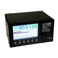
Spectrum Mode…
Mode Button: Changes mode.
CH Button: Selects among the 4 coupler channels. CH Auto is not offered in the Spectrum mode to avoid confusion. The channel selection for the
Spectrum mode is independent of the Power/SWR mode.
Range Button: Selects the desired vertical gain from 0 dB to 20 dB. The button turns red and an error message appears if the signal is too strong.
Power range is between 5W and 10KW in 11 steps, and also offers an Auto-Range choice. The selection is indexed to the current channel selection and
is saved in memory. The “Ref(dBm)” readout below the Filter button updates to indicate the current 0 reference level at the top of the graph.
Span Button: Selects the desired span width in Hz. The choices are 2, 5 and 10 kHz with a linear scale, and 2, 5 and 10 kHz with a log scale. Linear is
generally used for tests like two tone IMD. Log is best for frequency response measurements.
Averaging Button: Selects the amount of averaging applied to the display. A higher setting provides lower noise, but is slower to respond and update.
Test Tone Button: This button selects the desired test signal to be fed to the transmitter. Choices are same as Waveform Mode.
Touch Screen controls…
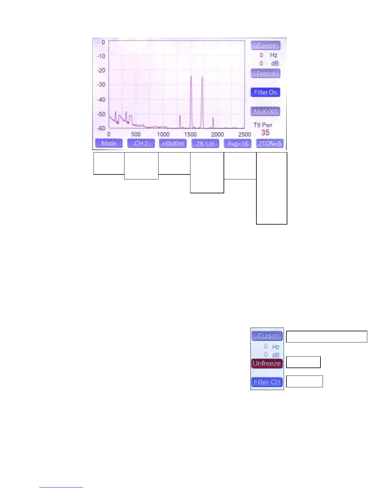
Cursor Button: Pressing this button cycles through three cursor modes… Cursor 1,
Cursor 2 and no cursor. Selecting Cursor 1 displays a blue crosshair, which allows the
user to set a position on the waveform in either amplitude or frequency, or both. The
corresponding amplitude and frequency are displayed numerically just below the Cursor
button. Selecting Cursor 2 adds a second cursor with green crosshairs. In this mode, the
numerical readout shows the amplitude and frequency difference between Cursor 1 and
Cursor 2. Pressing the cursor button again turns on the Peak Pwr Markers. The fourth
position is OFF.
Freeze Button: To aid in setting the cursors and making measurements,
pressing this button causes the waveform to freeze.
Filter Button: This button activates a 200 Hz filter, which eliminates the “carrier” generated by some of the test tones, and shifts the display by 200 Hz
to restore proper values to the frequency scale. The filter button is automatically selected when any test tone that uses the 200 Hz subcarrier is selected,
but the filter can be manually turned on or off with any test tone selection. A description of the use of the 200 Hz subcarrier is explained in the waveform
/ ‘scope section of the Quick Start Guide.
Ref Display: Indicates the maximum signal level at the top of the display (“0” reference). This changes as the gain control is adjusted. The choices are
+65 dBm, +55 dBm and +45 dBm (approx. 3 KW, 300 W, 30W).
Ttl Pwr Display: This indicates the transmitted signal level in dBm. Note, this is a total peak power reading and will not always match the graphic
display, because it represents the sum of the power in all the frequency bins, rather than the power in any given frequency bin.
Power/SWR
Waveform
Spectrum
2K Lin
5K Lin
10K Lin
2K Log
5K Log
10K Log
2 Tone+
Wnoise+
Pnoise+
2 Tone
WNoise
Pnoise
400 Hz
1 kHz
User 1
User 2
User 3
User 4
Cursor 1, Cursor 2, Peak Marker, Cursor Off
 Loading...