L
L
N
N
(T) 4A
230V~ +10%/-15%
50-60Hz
INPUT:
100-240V~, 1.52A
OUTPUT:
15V , 5A
L
N-V+V
OUT
BATT 2
12V/ 18Ah
-
red black
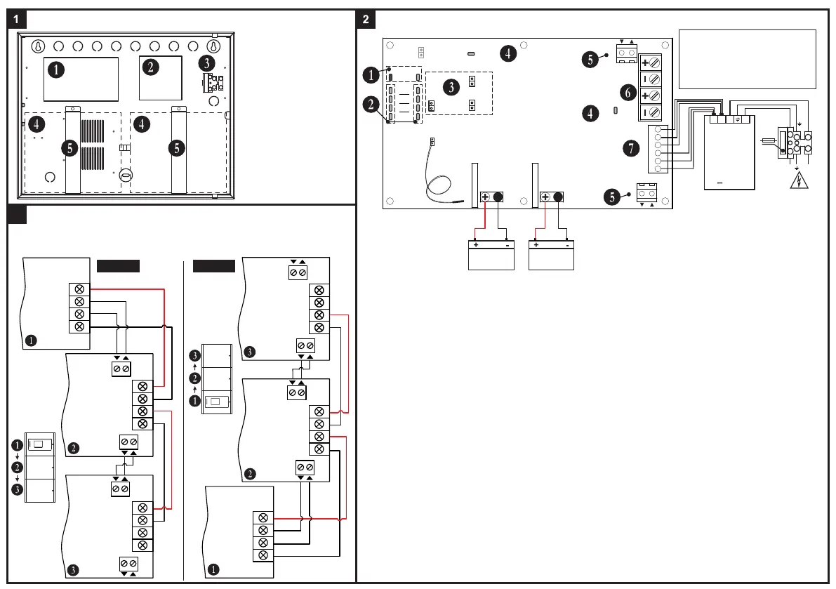
Elements
1 - Main board
2 - Power supply unit
3 - Main power supply
(terminal 230V~)
4 - Place for a battery
5 - Battery bracket*
* Note: The batteries must
be firmly tighten with the
brackets to the box bottom!
Batt 1
Dis
Batt 2
Dis
Tst
Ri
Dis
SYS FLT
OK FLT
AC
Ch FLT
Batt Los
Batt Low
Hi Resist
Batt 1
Batt 2
Temperature Sensor
(Place the temperature sensor
back or under any of the batteries.)
Fuse Batt1
Fuse Batt2
JP2 JP3
WRONG
CONNECTION
+POWER-
FLT
FLT
13.8V13.8V
IRIS PS72 Main Board
BATT 1
12V/ 18Ah
-
red black
1 - AC Indication for main power supply presence (230V~):
▪ “OK” LED (green) - Blinks at presence of main power supply.
▪ “FLT” LED (yellow) - Blinks at loss of main power supply.
2 - Battery Fault Indication. The indication is separated into two sections - Batt1 (Battery 1 connected to JP2 leads) and
Batt2 (Battery 2 connected to JP3 leads). The respective indicator starts blinking in case of following troubles:
▪ “Ch FLT” LED (yellow) - battery charging fault.
▪ “Batt Los” LED (yellow) - missing or deeply discharged battery (voltage lower than 10V ±10%).
▪ “Batt Low” LED (yellow) - discharged battery (voltage range 10V-11V ±10%).
▪ “Hi Resist” LED (yellow) - high battery resistance detected. Attention: The high battery resistance indication must
be enabled - no jumper set on “Ri Dis” terminal.
3 - Jumpers for disabling the operation:
▪ “Ri Dis” - Set a jumper to disable the indication for high battery resistance.
Attention: The disabling of High Battery Resistance indication is not in conformity with EN54 standard!
▪ “Batt 1 Dis” - Set a jumper to disable the operation of the battery connected to JP2 terminal.
▪ “Batt 2 Dis” - Set a jumper to disable the operation of the battery connected to JP3 terminal.
4 - System Fault Indication.
▪ “SYS FLT” LED (yellow) - lights on permanently in case of processor failure.
▪ “Wrong Connection” LED (yellow) - lights on permanently in case of reversed polarity of the connection between the
IRIS fire alarm panel power supply and JP4 terminal.
5 - FLT Terminals. Use the white and the grey wires from the spare parts kit to connect the FAULT IN and FAULT
OUT terminals of IRIS power supply to FLT terminal of IRIS PS72 as observing the polarity. The FAULT OUT output
will turn on when a problem with main power supply of the IRIS panel occurs. Connect the second FLT terminal of the first
IRIS PS72 to the FLT terminal of the second IRIS PS72 as observing the polarity, and so on. Attention: The FLT
terminals are short-circuited, so the wiring depends on the direction of the connection and the position of the
IRIS panel in the modular structure - see the connection diagrams.
6 - JP4 Terminal. Power supply terminals to IRIS fire alarm panel. Use the red and the black wires from the spare
parts kit to perform the connection as strictly observing the polarity - see the connection diagram.
7 - POWER Terminal factory connected to the main power unit of IRIS PS72.
Note: The “Tst” terminal is not used.
JP4
IN
IRIS PS72
Power block
GND
Fault Out
Fault In
+13.8V
IRIS
Power Supply
13.8V
- +
13.8V
- +
FLT
IRIS PS72
Main board
(first)
FLT
FLT
13.8V
- +
13.8V
- +
IRIS PS72
Main board
(second)
FLT
Connection Diagrams
3
IMPORTANT! If after powering up both the IRIS panel
and IRIS PS72 backup power supply, the LED
“WRONG CONNECTION” is lighting on you must
TURN OFF the power supply of both devices
immediately and check the polarity of the connection!
ATTENTION:
Observe the polarity of the
connection to the IRIS fire
alarm panel, batteries and
FLT terminals!
Figure 1 Figure 2
GND
Fault Out
Fault In
+13.8V
IRIS
Power Supply
13.8V
- +
13.8V
- +
FLT
IRIS PS72
Main board
(second)
FLT
FLT
13.8V
- +
13.8V
- +
IRIS PS72
Main board
(first)
FLT
NOTE: At FLT terminals, the arrows pointing inward the IRIS PS72 main board are
marking the terminals for input signals to the board, and the arrows pointing outward
are marking the terminals for output signals from the board.
Red
Black
Red
Black
 Loading...