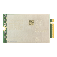
Thermal Design Guidelines
This section provides thermal design guidelines useful for developing a product with a Telit
FN990 modem.
Proper thermal protection design protects against human or component damage under
worst-case conditions.
Furthermore, it reduces the probability of failure and does not adversely affect the use of
the module, and greatly extends the operation time with maximum performance.
For more details, please refer to the thermal design guidelines.
Note: FN990 Family supports different RATs: 3G, 4G, and 5G Sub-6.
Based on the Radio Access Technology, the FN990 modem might exhibit high
current consumption, thus proper thermal designs are essential to dissipate heat
well.
Note: There is a large solder-resist opening area on the bottom side of the module.
Adding a TIM on that area with the solder-resist opening area is highly
recommended to ensure proper heat dissipation.
The modem temperature value can be read via AT command.
Note: For optimal RF performance, thermal dissipation, and mechanical stability,
the FN990 must be connected to the ground and metal chassis of the host board.
It is recommended that between the shield cover of the module and the heatsink
or the metal chassis of the host device use a TIM for better heat dissipation..
Power Supply PCB Layout Guidelines
As described in the electrical design guidelines, a low ESR capacitor should be connected
to the power supply output to reduce current peaks. A protection diode on the modem
power supply input should be connected to protect the FN990 from spikes and polarity
inversion.
Placement of these components is crucial for correct operation: a misplaced component
can badly affect power supply performance:
•
The bypass low ESR capacitor must be placed close to the FN990 power
input pins or - if the power supply is of a switching type - it can be placed
close to the inductor to reduce ripple, as long as the PCB trace from the
capacitor to FN990 is wide enough to avoid significant voltage drop even
during the 4A current peaks.
•
The protection diode must be placed close to the modem connector.
•
The PCB traces from the input connector to the power regulator IC must
be wide enough to ensure that no voltage drops occur during the 4A
current peaks.

 Loading...