Figure 15: Example Circuit for WLAN/GNSS Disable Function
Please refer to the AT commands guide for setting the WLAN/GNSS disable function.
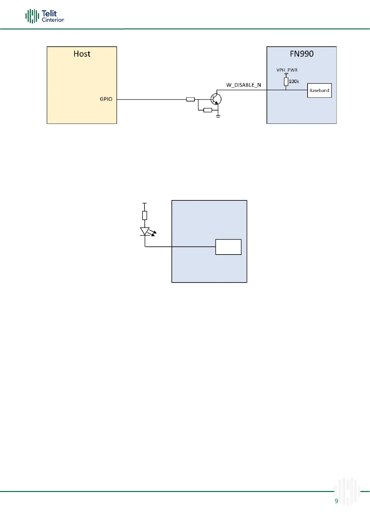
LED
The LED signal drives the LED output. The recommended LED connection is the following:
Figure 16: Recommended LED Connection
R1 and VDD determine the LED brightness and forward current.
When VDD is 3.3V and LED’s forward voltage is 2.0V, the recommended R1 value ranges
from 66 to 250 Ohm.
However, the resistor value must be calculated considering the LED specifications. It is
recommended to use VDD below the VPH_PWR level.
Note: If the LED function is enabled and a LED is connected to the LED_N pin,
current consumption may be slightly increased. And current sinking mode (up to
10mA) can be supported.
Wake Host
WAKE_ON_WAN_N is an active low signal and is used to wake the Host when specific
events occur.
•
SMS
•
Network de-registration
•
Voice Call
Please refer to the AT commands guide for setting the Wake function.

 Loading...