FN990 Family Hardware Design Guide
Note: GNSS receive path uses either the dedicated GNSS connector or the shared
Secondary AUX antenna connector.
8.5 GNSS Receiver
The FN990 Family integrates a GNSS receiver that can be used either in Standalone or in
A-GPS (assisted GPS) mode.
FN990 modems support active GNSS antennas.
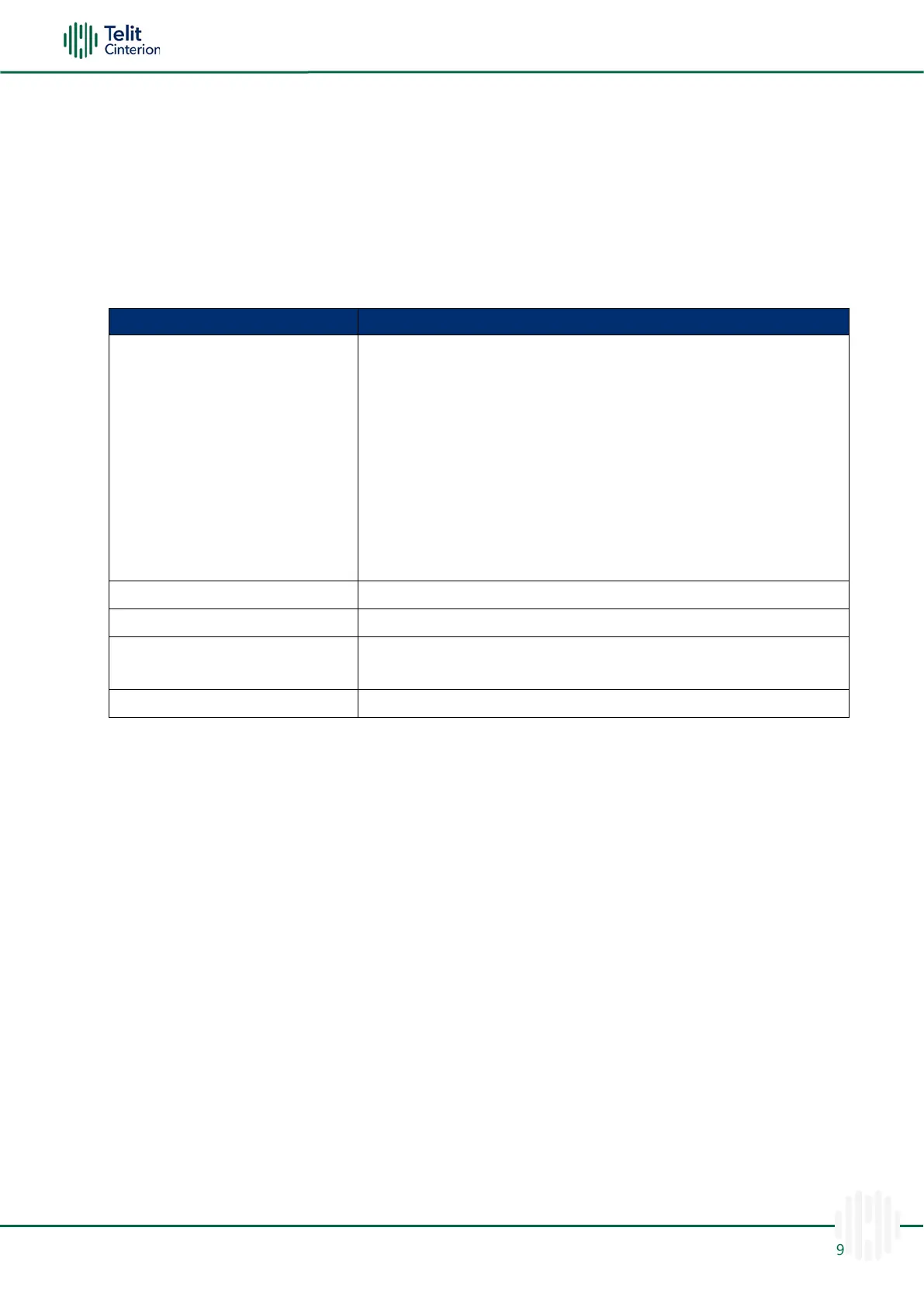
Table 45: GNSS Receiver
Wide-band GNSS:
1559 – 1606 MHz recommended
GPS:
2.046 MHz BW NB GPS (centered on 1575.42 MHz)
Glonass (GLO):
~ 8.3 MHz BW (1597.05 ~ 1606 MHz)
BeiDou (BDS):
4.092 MHz BW (1559.05 ~ 1563.14 MHz)
Galileo (GAL):
4.092 MHz BW (centered on 1575.42 MHz)
External Amplification Gain
7.5 dB < Gain < 26 dB for nominal performance
2,3
1.5 dB < Gain < 7.5 dB for nominal performance
4,5
Note:
1
Configured as AT$GPSANTPORT= 1 or 2 (Internal LNA Active in either configuration)
2
Configured as AT$GPSANTPORT= 3 (Internal LNA bypassed)
3
Must not exceed 26 dB
4
Configured as AT$GPSANTPORT= 4 (Internal LNA active)
5
Must not exceed 7.5 dB
Total gain applied at FN990 RF input connector (Passive Antenna gain + External LNA
gain-losses)
GNSS RF Front-End Design
The FN990 Family contains an integrated LNA and front-end SAW filter.
This allows the module to operate properly with a passive GNSS antenna. If the antenna
cannot be located near the FN990, then an active antenna (that is, an antenna with a built-
in low noise amplifier) can be used with an external dedicated power supply circuit.
GNSS receive path uses either the dedicated GNSS connector #4 or the shared antenna
connector #1.

 Loading...