D
dianagrayAug 14, 2025
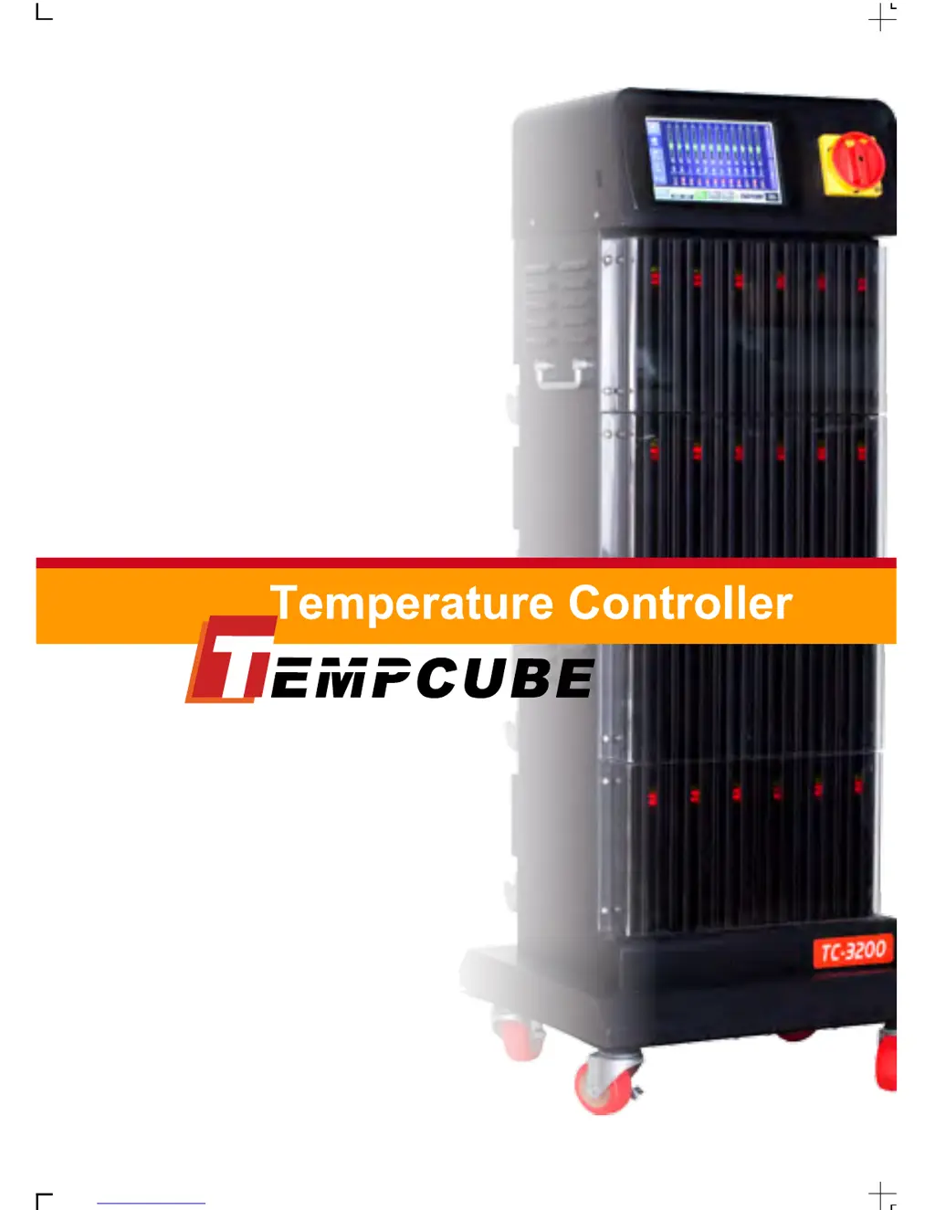
How to fix Tempcube TC-3200 Lite Temperature Controller when temperature rises continuously?
- YymorrisAug 15, 2025
If the temperature rises continuously, it may be due to a damaged TRIAC attached to the heat sink of the controller. Check the pins on the TRIAC; if two or three pins are shorted, the TRIAC is malfunctioning.