TENNEY ENVIRONMENTAL
WATLOW
93
-
TEMPGARD
IV
CONFIGURATION
&
USE
(Optional)
-
I
As an option, your chamber may include the TempGard IV feature with the Watlow
93
Controller. The circuit operation description is explained in the Alarm And Shutdown Circuit
section of this manual. This configuration section serves as a brief reference guide. For
complete details of the Watlow
93
Controller, please reference the user manual.
When properly configured, the lower display of the control will be blank and the upper display
will show the actual temperature as measured by the control's RTD sensor, when conditions
are within the alarm settings. If an out of limit condition occurs, the lower display will flash "HI"
or
"LO"
depending on the particular fault.
IMPORTANT:
ForAll Models
-
When the alarm has cleared you must press the
RESET pushbutton
1
PB.
To configure the control to perform as described above, power it up and select the setup menu
by pressing the
UPIDown arrow keys simultaneously. Pressing the
"M"
key then allows you to
scroll through the set up parameters.
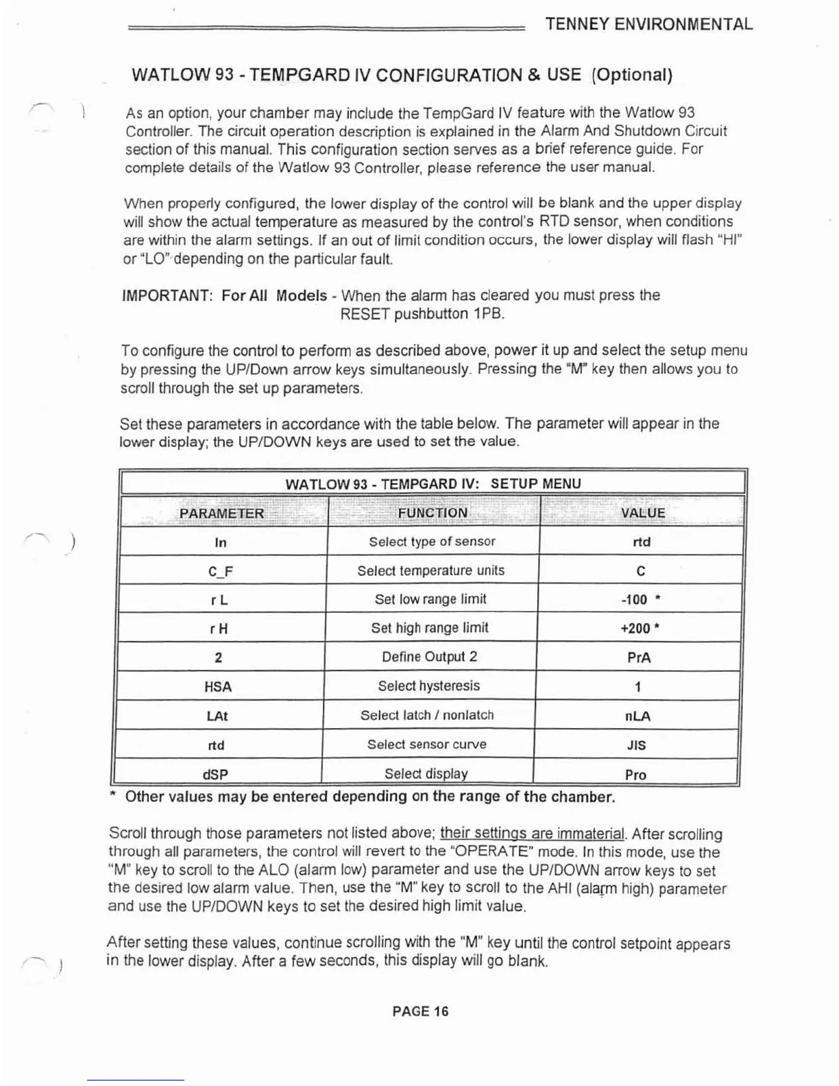
Set these parameters in accordance with the table below. The parameter will appear in the
lower display; the
UPIDOWN keys are used to set the value.
WATLOW
93
-
TEMPGARD IV: ENU
-.--.-I
PARAMETER
,
-
In
11
r
H
1
Set high range limit
1
+200
11
c-F
r
L
11
2
1
Define Output
2
I
PrA
11
FUNCTION
II
Select
type
of
sensor
11
HSA
I
Select hysteresis
1
1
11
VALUE
ltd
Select temperature units
Set low range limit
C
-100
'
dSP
I
Select display
I
Pro
Other values
may
be entered depending on the range of the chamber.
LAt
ltd
Scroll through those parameters not listed above; their settinos are immaterial. After scrolling
through all parameters, the control will revert to the "OPERATE" mode. In this mode, use the
"M"
key to scroll to the ALO (alarm low) parameter and use the UPIDOWN arrow keys to set
the desired low alarm value. Then, use the
"Mu
key to scroll to the AH1 (alam high) parameter
and use the
UPIDOWN keys to set the desired high limit value.
After setting these values, continue scrolling with the
"M"
key until the control setpoint appears
-
1
in the lower display. After a few seconds, this display will go blank.
Select latch
I
nonlatch
Select sensor curve
--
nLA
JIS
 Loading...