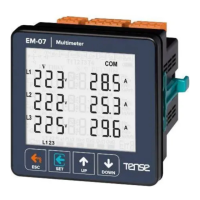
The EM-07D is a sophisticated digital multimeter designed for comprehensive monitoring of 3-phase voltage and 3-phase current transformer systems. It provides detailed measurements of minimum, maximum, average, and demand values for various parameters, including voltage, current, frequency, and power. The device features an adjustable display for high/low voltage, current, and frequency, making it adaptable to diverse system requirements. It also incorporates a 1x relay output for control applications and offers robust protection features for voltage, current, and frequency, along with phase sequence protection. The EM-07D supports RS485 Modbus RTU communication, allowing for integration into larger monitoring and control systems. Its user-friendly interface includes a custom design glass LCD for clear display of information and easy navigation through menus.
Technical Specifications:
- Operating Voltage: 85V - 240V AC
- Operating Frequency: 50/60 Hz
- Operating Power: <10VA
- Operating Temperature: -20°C ... 55°C
- Voltage Input: 5V - 300V AC
- Voltage Measurement Range: 5V - 300kV
- Current Input: 50mA - 5.5A
- Current Measurement Range: 50mA - 10.000A
- Voltage, Current Accuracy: %±1
- Supported Connection: 3P4W
- Current Transformer Ratio: 1...2000
- Voltage Transformer Ratio: 1...999
- Communication: RS485 MODBUS RTU (1200 - 38400bps)
- Display: 71.5 x 61.5mm Custom Design Glass LCD
- Output: 2A / 250V AC (Resistive Load)
- Weight: <300gr.
- Protection Class: IP41 (Panel), IP20 (Body)
- Panel Hole Size: 91mm x 91mm
- Connection Type: Plug-in Connection
- Cable Diameter: 1.5mm²
- Installation: Front panel mounted
- Operating Altitude: <2000 meters
Usage Features:
The EM-07D's display provides comprehensive information at a glance. The Home Screen shows current voltage and current values together. If protection type is L-N, it shows phase-neutral voltage; otherwise, it shows phase-phase voltage. The device displays minimum, maximum, average, and demand values for various parameters across all three phases. Users can navigate through different display screens using the "Up" and "Down" buttons to view current values, minimum values, maximum values, demand values, and frequency values for each phase.
The device features a menu-driven interface for configuration and settings.
- ESC Button: Returns to the home screen, exits menu, saves and cancels changes, and performs a manual reset.
- SET Button: Enters menu, saves changes, and moves to the next menu state.
- UP Button: Navigates to a main measurement value, then to menu parameters, and increases parameter values.
- DOWN Button: Navigates to a deep measurement value, then to menu parameters, and decreases parameter values.
Error Codes:
The EM-07D provides detailed error codes to assist in troubleshooting:
- Err0: Phase Sequence ERR
- Err1: High Voltage ERR
- Err2: Low Voltage ERR
- Err3: High Current ERR
- Err4: Low Current ERR
- Err5: High Frequency ERR
- Err6: Low Frequency ERR
- Err7: Demurrage ERR
- Err8: Voltage Fuses ERR
- Err9: Current Fuses ERR
- ErrA: Asymmetry Voltage ERR
- Errb: Asymmetry Current ERR
In case of an error, the relay will open, and the backlight will flash, displaying the error code in the bottom-right corner.
The device offers various display screens for detailed monitoring:
- Home Screen: Shows voltage and current values.
- Figures 3-6: Display phase-neutral minimum, maximum, average, and demand voltage values.
- Figures 7-10: Display phase-phase minimum, maximum, average, and demand voltage values.
- Figures 11-15: Display current minimum, maximum, average, and demand values for each phase.
- Figures 16-20: Display apparent power minimum, maximum, average, and demand values for each phase.
- Figures 21-24: Display frequency minimum, maximum, average, and demand values for each phase.
The settings menu allows users to configure various parameters:
- Figure 25 (PASS 0000): Enter password to access program list.
- Figure 26 (VOLTAGE SET): Voltage settings.
- Figure 27 (CURRENT SET): Current settings.
- Figure 28 (FREQ SET): Frequency settings.
- Figure 29 (RS485 SET): RS485 settings.
- Figure 30 (GENERAL SET): General settings.
- Figure 31 (ABOUT): Device information.
The voltage settings menu allows configuration of various voltage protection parameters:
- Pr.1 High Voltage Protection Value: Determines the maximum operating voltage value of load. Default: 250V, Min: 1V, Max: 300V.
- Pr.2 High Voltage Protection Delay Time: Determines delay open time. Default: 3sec, Min: 1sec, Max: 10000sec.
- Pr.3 High Voltage Protection Reset Time: Determines delay close time. Default: 3sec, Min: 1sec, Max: 10000sec.
- Pr.4 High Voltage Protection Hysteresis: Required hysteresis for high voltage warning. Default: 5V, Min: 1V, Max: 200V.
- Pr.5 High Voltage Protection Enable/Disable: Enables or disables high voltage protection. Default: Enable.
- Pr.6 Low Voltage Protection Value: Determines the minimum operating voltage value of load. Default: 170V, Min: 1V, Max: 300V.
- Pr.7 Low Voltage Protection Delay Time: Determines delay open time. Default: 3sec, Min: 1sec, Max: 10000sec.
- Pr.8 Low Voltage Protection Reset Time: Determines delay close time. Default: 3sec, Min: 1sec, Max: 10000sec.
- Pr.9 Low Voltage Protection Hysteresis: Required hysteresis for low voltage warning. Default: 5V, Min: 1V, Max: 200V.
- Pr.10 Low Voltage Protection Enable/Disable: Enables or disables low voltage protection. Default: Enable.
- Pr.11 Voltage Asymmetry Protection Value: Determines the controlled voltage asymmetry. Default: %20, Min: %5, Max: %30.
- Pr.12 Voltage Asymmetry Protection Delay Time: Determines delay open time. Default: 3sec, Min: 1sec, Max: 10000sec.
- Pr.13 Voltage Asymmetry Protection Reset Time: Determines delay close time. Default: 3sec, Min: 1sec, Max: 10000sec.
- Pr.14 Voltage Asymmetry Protection Hysteresis: Required hysteresis for voltage asymmetry warning. Default: %2, Min: %1, Max: %10.
- Pr.15 Voltage Asymmetry Protection Enable/Disable: Enables or disables voltage asymmetry protection. Default: Enable.
- Pr.16 Voltage Auto Reset Enable/Disable: If auto reset enable and system into error, all voltage are over/below the protect value as hysteresis value, relay output switches on at the end of the Reset time. If auto reset is disable, after all voltage are over/below hysteresis value, relay output switches manually. Default: Enable.
- Pr.17 Voltage Transformer Ratio: If using medium voltage, you can use VTR. Default: 1, Min: 1, Max: 999.
- Pr.18 Voltage Fuses Enable/Disable: If any phase voltage exceeds 1.5 times of high voltage protect values, or if any phase voltage decrease 0.5 times of low voltage protect value, the relay switches off instantly. At position disable, voltage fuses function is cancelled. Default: Disable.
- Pr.19 Voltage Protection Type: Voltage Protection can be selected as L-N or L-L. Default: L-n.
The current settings menu allows configuration of various current protection parameters:
- Pr.20 High Current Protection Value: Determines the maximum operating current value of load. Default: 3.0A, Min: 0.1A, Max: 5.0A.
- Pr.21 High Current Protection Delay Time: Determines delay open time. Default: 3sec, Min: 1sec, Max: 10000sec.
- Pr.22 High Current Protection Reset Time: Determines delay close time. Default: 10sec, Min: 1sec, Max: 10000sec.
- Pr.23 High Current Protection Hysteresis: Required hysteresis for high current warning. Default: 0.5A, Min: 0.1A, Max: 3.0A.
- Pr.24 High Current Protection Enable/Disable: Enables or disables high current protection. Default: Enable.
- Pr.25 Low Current Protection Value: Determines the minimum operating current value of load. Default: 0.1A, Min: 0.1A, Max: 5.0A.
- Pr.26 Low Current Protection Delay Time: Determines delay open time. Default: 3sec, Min: 1sec, Max: 10000sec.
- Pr.27 Low Current Protection Reset Time: Determines delay close time. Default: 10sec, Min: 1sec, Max: 10000sec.
- Pr.28 Low Current Protection Hysteresis: Required hysteresis for low voltage warning. Default: 0.5A, Min: 0.1A, Max: 3.0A.
- Pr.29 Low Current Protection Enable/Disable: Enables or disables low current protection. Default: Disable.
- Pr.30 Current Asymmetry Protection Value: Determines the controlled current asymmetry. Default: %30, Min: %5, Max: %50.
- Pr.31 Current Asymmetry Protection Delay Time: Determines delay open time. Default: 3sec, Min: 1sec, Max: 10000sec.
- Pr.32 Current Asymmetry Protection Reset Time: Determines delay close time. Default: 10sec, Min: 1sec, Max: 10000sec.
- Pr.33 Current Asymmetry Protection Hysteresis: Required hysteresis for current asymmetry warning. Default: %3, Min: %1, Max: %20.
- Pr.34 Current Asymmetry Protection Enable/Disable: Enables or disables current asymmetry protection. Default: Disable.
- Pr.35 Current Auto Reset Enable/Disable: If auto reset enable and system into error, all current are over/below the protect value as hysteresis value, relay output switches on at the end of the Reset time. Default: Enable.
- Pr.36 Current Transformer Ratio: If a current transformer has a ratio of 100/5A is used between the system and device; Current transformer ratio is entered as 100/5 = 20. If the current transformer is not used between the system and device, current transformer ratio is entered as "1". Default: 1, Min: 1, Max: 2000.
- Pr.37 Current Fuses Enable/Disable: If any phase current exceeds 1.5 times of high current protect value, or if any phase current decrease 0.5 times of low voltage protect value, the relay switches off instantly. Default: Disable.
- Pr.38 Demurrage Protection Enable/Disable: Enables or disables the demurrage protection. Default: Enable.
- Pr.39 Demurrage Protection Time: Demurrage time is used to prevent from faulty switching caused by motor demurrage current. Default: 10, Min: 1, Max: 100.
- Pr.40 Demurrage Protection Factor: Demurrage current is 3-5 times more than normal operating current consumption. Default: 3.0, Min: 1.0, Max: 10.0.
The frequency settings menu allows configuration of various frequency protection parameters:
- Pr.41 High Frequency Protection Value: Determines the maximum operating frequency value of load. Default: 51Hz, Min: 45.0Hz, Max: 70.0Hz.
- Pr.42 High Frequency Protection Delay Time: Determines delay open time. Default: 3sec, Min: 1sec, Max: 10000sec.
- Pr.43 High Frequency Protection Reset Time: Determines delay close time. Default: 3sec, Min: 1sec, Max: 10000sec.
- Pr.44 High Frequency Protection Hysteresis: Required hysteresis frequency for high frequency warning. Default: 0.5Hz, Min: 0.1Hz, Max: 20.0Hz.
- Pr.45 High Frequency Protection Enable/Disable: Enables or disables high frequency protection. Default: Disable.
- Pr.46 Low Frequency Protection Value: Determines the minimum operating frequency value of load. Default: 49Hz, Min: 45.0Hz, Max: 70.0Hz.
- Pr.47 Low Frequency Protection Delay Time: Determines delay open time. Default: 3sec, Min: 1sec, Max: 10000sec.
- Pr.48 Low Frequency Protection Reset Time: Determines delay close time. Default: 3sec, Min: 1sec, Max: 10000sec.
- Pr.49 Low Frequency Protection Hysteresis: Required hysteresis frequency for low voltage warning. Default: 0.5Hz, Min: 0.1Hz, Max: 20.0Hz.
- Pr.50 Low Frequency Protection Enable/Disable: Enables or disables low frequency protection. Default: Disable.
- Pr.51 Frequency Auto Reset Enable/Disable: If auto reset enable and system into error, all frequency are over/below the protect value as hysteresis value, relay output switches on at the end of the Reset time. Default: Disable.
The RS485 settings menu allows configuration of communication parameters:
- Pr.52 Modbus ID: Determines Modbus device ID. Default: 1, Min: 1, Max: 247.
- Pr.53 Baudrate Selection: Determines Modbus communication speed. Default: 9600bps, Min: 1200bps, Max: 38400bps. Note: Stopbits: 1, Parity: none and Databits: 8.
The general settings menu allows configuration of general device parameters:
- Pr.54 Password Change: This menu is used for changing the user password. Default: 0000, Min: 0000, Max: 9999.
- Pr.55 Password Protection Enable/Disable: This menu is used for activating the user password. Default: Disable.
- Pr.56 Phase Sequence Protection Enable/Disable: This menu is used to device with phase sequence or without phase sequence function. Default: Disable.
- Pr.57 Demand Time: Determines demand calculate time. Default: 15min, Min: 1min, Max: 120min.
- Pr.58 Demand Record Delete: You can delete demand and average records. If cut off device energy min,max, average and demand values are deleted.
- Pr.59 Current Transformer Cable Turn Number: User defines the turn number, which is the number of how much tour the current cable has rounded into the current transformer. Default: 1, Min: 1, Max: 20.
The About menu displays device information:
- Pr.61 Serial Number: Displays the device's serial number.
- Pr.62 Version: Displays the device's software version.
Maintenance Features:
- De-energize and Disconnect: Before any maintenance, de-energize and disconnect the device.
- Cleaning: Clean the body of the device with a dry or damp-dry cloth. Do not use conductive or other chemical substances as a cleaning agent that can damage the device. After cleaning, make its connections and check whether it is working by energizing it.
- Current Transformer Value: Ensure the current transformer value is higher than the maximum current drawn from the system.
- Wiring: Prevent any mistake while connecting the output terminals of the current transformer by using cables in different colors for each phase or designating a number for each cable. Keep the cables connected to the output terminals of the current transformer away from the high-voltage line.
- Current Transformer Shake: To prevent any shake on the current transformer, fix it on the bus-bar, cable, or rail.
- LCD Display: Do not expose the LCD display directly to sunlight to avoid any harm.
- Temperature Level: Note that the temperature level on the panel to which the device is mounted is at the range of operating temperature of the device (-20°C...55°C).
- Installation Space: There must be a space of 5cm behind the device after its installation.
- Front-Cover: Fix the device securely to the front-cover of the panel with the apparatus delivered together with the device.
- Humidity: Ensure that the panel to which the device is mounted does not operate in a humid environment.
- Switch/Circuit Breaker: Place the switch or circuit breaker close to the device or in a location that is easily accessible for the operator.
- System Installation: Place a switch or circuit breaker on the system during installation of the device.
- Cables: Note that the cables must not be energized during installation. Flexible monitored and twisted cables must be used for the input and output lines which are not connected to the mains.
- Technical Personnel: The technical personnel according with the instructions specified in the user's manual must perform installation of the device and electrical connections.
- Feeder Cables: The feeder cables must be compatible with the requirements of IEC 60227 or IEC 60245.