Lock in OFF Operation
●操作スイッチ定格の値は、Uc の値に関わらず共通です。
T2MC 4 0B
切替レバー
Select lever
手動 Manual
電動 Motorized
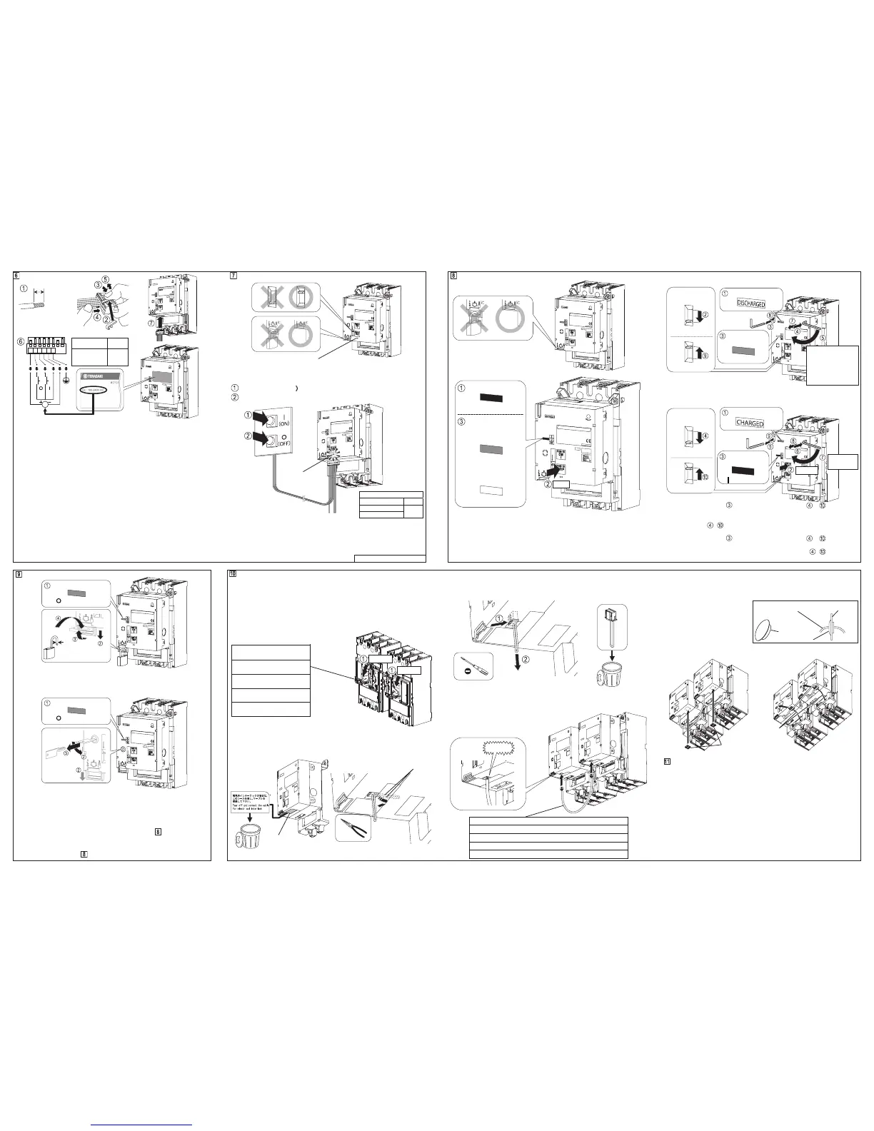
結線
・表示された電圧の電源(Uc)を接続して下さい。電圧は以下の仕様があります。
・Supply voltage specification (Uc) is shown on the nameplate. Supply voltage type is as
follows depending on the ordered motor.
●100-240V AC
・+,-の記号は,直流電源仕様の場合の極性を示します。
・Polarity symbols "+" and "–" apply to DC power supply.
・電線は,構造物に結束するなどの方法でコネクタプラグに荷重が掛からない
よう施工して下さい。
・Electric wires must be routed and tied in such a way that connectors are not strained.
・自動リセット(オプション)付電動操作装置は,電源(Uc)を与えると自動的
に遮断器のリセット操作を開始します。
・The auto reset feature (optional) allows the breaker to be reset automatically when the power
Uc is applied to the Motor Operator and the breakers in tripped by means.
・電動操作時,近くで使用される機器に障害を与えることがありますが,この
場合,入力側にノイズフィルター等を取付けて下さい。
・The Motor Operator when actuated can cause interference to adjoining devices. To prevent
such an interference, use a noise filter at the input side.
2G0701SAD (KRB-0519d)
オフロック操作
・南京錠はご用意下さい。
・The padlock is not supplied.
・解除はロック操作の逆手順で行います。
・When unlocking, proceed in reverse order of locking.
・解除はロック操作の逆手順で行います。
・When unlocking, proceed in reverse order of locking.
・ロック解除時,キーは抜けません。
・The key cannot be removed when the off lock is released.
・
電気的インターロックケーブルを接続している場合,一方の電動操作装置をオフロックす
ると他方の電動操作装置は電動操作が出来なくなります。オフロックしていない側の電動
操作装置を操作する場合は手動操作を行ってください。(詳細は を参照下さい。)
・When motor operators are connected by electrical interlock cable, motorized operation is
disabled if one motor operator is locked. When to operate unlocked motor operator, operate
in manual operation (refer to
).
電動操作 Motorized Operation
・“×”の場合,電源ランプは点灯せず,電動操作は行えません。
・X: The power lamp remains off and motorized operation is disabled.
┃(ON)操作 ┃(ON) Operation
○(OFF),リセット操作 ○(OFF), RESET Operation
操作時間 Operating time
┃(ON) ≦0.1s
○(OFF)
リセット RESET
≦1.5s
・自動リセット付の場合,遮断器が○(OFF)状態の時にトリップ操作を連続し
て行わないで下さい。RESET 操作が繰り返されて,故障のおそれがあります。
・In the case of Automatic reset , do not attempt to trip the breaker from the ○(OFF) state.
Repeating the trip from the ○(OFF) scate can cause malfunction.
電気的インターロック用ケーブルの取付(オプション)
Mounting procedure of Electrical interlock cable (Option)
・機械的インターロック装置を併用する場合は必ず電気的インターロックを併
用して下さい。
・For mechanically interlocked breakers, use electrical interlock cable as well.
◯
1 右側及び左側の遮断器を○(OFF)にします。
◯
1 Turn OFF the right-side and left-side of breaker.
機械的インターロック装置
Mechanical interlock device
T2ML40B(リンク式)
(Link type)
T2MW40(ワイヤー式)
(Wire type)
T2ML80 (リンク式)
(Link type)
T2MW80(ワイヤー式)
(Wire type)
※図はT2ML40B形リンク式インターロック装置付を示します。
Figure shows the link type mechanical interlock device of T2ML40B.
◯
2 電動操作装置からシールを剥します。
◯
3
ダミーコネクタの線を引出します。
◯
2 Tear off the seal from the Motor operator.
◯
3 Pull on the cable of the dummy connector.
手動操作 Manual Operation
・“×”の場合,手動操作は行えません。
・X: Manual operation is disabled.
トリップ操作 TRIP Operation
・遮断器が○(OFF)状態の時,トリップ操作は行わないで下さい。誤ってト
リップ操作を行った際は,まず┃(ON)操作を行い(遮断器は┃(ON)しま
せん),次に○(OFF)操作を行ってリセットして下さい。
・Do not attempt to trip the breaker when it is in an OFF state. If improper TRIP operation was
attempted, perform ON operation (the breaker will not turn on) and then OFF operation to
reset the breaker.
◯
4 マイナスドライバーでダミーコネクタの爪を押して掛りを外し、ダミーコネ
クタを抜き取ります。
◯
4 Release the latch of the dummy connector and pull it out connector.
◯
5 電動操作装置を取付けます。詳細は□
5
を参照下さい。
◯
5 Mounting the Motor operator. For detailed, refer to □
5
.
◯
6 電動操作装置に電気的インターロック用ケーブルを接続します。
◯
6 Connect the erectrical interlock cable to Motor Operators.
○(OFF),リセット操作 ○(OFF), RESET Operation
・六角棒レンチが取外しにくいときは,
マイナスドライバーでこじって取外して下さい。
・If the allen key is hard to remove, pry it with a flatblade screwdriver.
┃(ON)操作 ┃(ON) Operation
・電源ランプ消灯状態で
┃(ON)操作を行った場合, ~ の操作を行
わないと,遮断器がトリップした際,電動操作装置はトリップ表示を行い
ません。
・Neglecting steps after performing ON operation with the power lamp being off will
prevent the Motor Operator from providing a "Tripped" indication when the breaker trips open.
・電源ランプ点灯状態で ┃(ON)操作を行った場合, ~ の操作は不
要です(電動操作装置が自動的に行います)。
・When ON operation is performed while the power lamp is ON, steps are
automatically performed by the Motor Operator.
◯
7 2台の遮断器間に隔壁がある場合,防塵ブッシュを隔壁に取付けます。(防
塵ブッシュの取付穴径はφ28mm,隔壁の取付許容厚は 1≦t≦3.2 mm です。)
◯
7
If there is a partition between the two breakers, install
Dust-proof bushing
in the partition.
(Dust-proof bushing requires a mounting hole of 28 mm in diameter bored in the 1 mm to 3.2
mm thick partition).
◯
8 束線バンド固定具を貼付けます
◯
8 Stick the Cable tie mounts on the cover.
◯
9 束線バンド固定具の穴に束線バンドを通し,ケーブルを固定します。
◯
9
Fit a cable tie through hole of the Cable tie mounts and fix the cable by securing the cable tie.
異常現象発生時の電源ランプの点滅について
About power indicator flashing when the following occur
以下の異常現象が発生した場合に電源ランプ(□
7
参照)が点滅します。
1.電気的インターロックケーブルの導通不良
電気的インターロックケーブルの断線,接続不良,等。
2.電動操作不良
電動操作装置の取付不良,電動操作機構故障,等。
この場合は,いったん電源を切った後,原因を取り除いてから再度電動操
作して下さい。
Power indicator(refer to □
7
) f lashes when the following troubles occurred.
1. Failure continuity of electrical interlock cable
Breaking of wire, Failure of connection of electrical interlock cable, etc.
2.Failure of motorized operation
Failure of mounting, Failure of motorized operation mechanism, etc.
In this case,remove the cause after control power is off, then perform motorized operation again.
┃(ON)
約 180°
Approx.180°
切替レバー
Select lever
手動
Manual shutter opener
電動 Motorized
表示確認
Check indicator
電源ランプ Power indicator
防塵ブッシュ
Dust-proof bushing
電気的インターロックケーブル
Electrical interlock cable
隔壁
Partition
CLICK!
束線バンド固定具
Cable tie mounts
束線バンド
Cable tie
シール
Seal
φ5.5-8
Max ×3
点灯
TRIP
表示確認
Check indicator
表示確認
Check indicator
┃(ON)(赤 Red)
○(OFF), RESET
約 2.5 回転
(止まるまで回して下さい)
Approx. 2.5 turns
(Turn the allen key until
it stops)
表示確認
Check indicator
○(OFF)(緑 Green)
表示確認 Check indicator
┃(ON)(赤 Red)
表示確認 Check indicator
電源ランプ点灯時
When power lamp is on:
○(OFF)(緑 Green)
電源ランプ消灯時
When power lamp is off:
TRIP(白 White)
表示確認 Check indicator
○(OFF)(緑 Green)
表示確認 Check indicator
○(OFF)(緑 Green)
電線
Wire
○(OFF)
○(OFF)
●100-120V DC
●
24-48V DC
8-9mm
0.8-2mm
2
(AWG18-14)
 Loading...