Do you have a question about the Teseq NSG 5500 and is the answer not in the manual?
Defines different levels of safety instructions with symbols, signal words, and consequences.
Explains warning symbols and signal words used on the test system for specific risks.
Specifies the excess voltage category for the NSG 5500 test system per IEC 60664.
States that these instructions are valid for the complete installation and do not suspend other regulations.
Details the function of the SYSTEM STOP button and its safety implications during operation.
Outlines general precautions and specific instructions for safe operation of the test equipment.
Specifies that the generator must be operated by qualified and authorized personnel only.
Assigns responsibility for safety measures to the owner, supervisor, and operator of the equipment.
References relevant safety standards like EN 50191, IEC 348, and ISO 9001 for electrical test installations.
Instructs to shut down and label equipment if safety is compromised, requiring service personnel.
Defines the agreed use of the tester exclusively for simulation of automotive EMC events.
Provides general safety advice, including restrictions to authorized specialists and handling of output connections.
Covers installation requirements, including protective earth connections, environmental conditions, and safety precautions.
Details safety requirements during test execution, including access control and protective measures for the DUT.
Lists potential dangers associated with the generator, such as disruptions, arcing, and RF radiation.
Highlights dangers related to the Device Under Test (DUT), including damage, fire, and fragmentation risks.
Instructions for inspecting shipment for damage and reporting any defects found upon receipt.
Lists standard delivery items for the NSG 5500 and mentions optional modules and equipment.
Specifies the required operating position for the NSG 5500 to ensure stability and safety.
Details requirements for connecting the NSG 5500 to line voltage and ensuring proper grounding for safety.
Explains how to set the regional input voltage range (110-120 V or 220-240 V) using the selector.
Provides a checklist for powering up and putting the NSG 5500 into service, emphasizing safety.
Guides the user through the installation and setup process for the FT 5531 burst generator module.
Describes the recommended test setup for checking the integrity of FT 5531 output pulses using an oscilloscope.
Illustrates reference points used for parameter specifications of the FT 5531 output pulses.
Details the installation and setup process for LD 5505 and LD 5550 load dump generator modules.
Presents the test setup for verifying the output pulse integrity of LD 5505/5550 modules with an oscilloscope.
Shows the reference points for parameter specifications on the LD 5505/5550 modules for pulse generation.
Guides through the installation and setup procedures for the MT 5511 micro transient generator module.
Outlines the test setup for checking the output pulse integrity of the MT 5511 module using an oscilloscope.
Displays reference points for parameter specifications of pulses generated by the MT 5511 module.
Covers the installation and setup of the control unit (CTR) for the NSG 5500 system.
Explains how to set the IEEE address for communication with the control unit.
Details setting the IEEE address for the CTR 5500 using its DIP switch array for AutoStar communication.
Describes setting the GPIB address for CTR 5501/5502 using the Flash Loader Tool via USB.
Provides instructions and cautions for updating the NSG 5500 system firmware.
Explains how to update the CTR 5500 firmware from within the AutoStar software.
Guides updating CTR 5501/5502 firmware using the controller update tool from the AutoStar CD.
States that no specific installation procedure is required for firmware files, just copying the exe file.
Describes the initial screen and disabled buttons during the loader application's initialization phase.
Explains how to handle startup errors related to invalid COM ports and select the correct COM port.
Details the process of clicking buttons to retrieve firmware versions and select firmware image files.
Describes the two steps involved in downloading firmware: reading the file and erasing/writing new firmware.
Explains the recovery procedure for situations where a communication error occurs during firmware download.
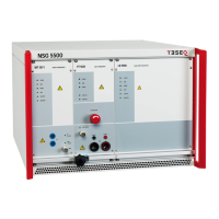
Provides a general overview of the NSG 5500 system and its various modules.
Covers the operation of the NSG 5500 EMC test system, including its capabilities and standards compliance.
Introduces the NSG 5500 as a modular instrument for automotive EMC testing, meeting various standards.
Details the procedure for powering up the NSG 5500 system, including boot time and safety warnings.
Describes the NSG 5500 mainframe and its system support electronics plugged in from the rear.
Explains the function of the CDN 5500 unit for mains input, fuses, and battery switching.
Details the control unit housing the processor and remote control interfaces for the NSG 5500.
Describes the CTR 5502 and its capability to house up to eight ARB 5500 arbitrary waveform generators.
Explains the HV-supply unit's role in charging pulse generators with high energy bursts.
Presents a system block diagram illustrating the connections between various NSG 5500 modules.
Details the input/output signals on the NSG 5500 mainframe for synchronization with external equipment.
Describes the pin assignment for the "REMOTE" connector used for start/stop signals with CTR 5500.
Explains the DUT FAIL input signal, used to indicate DUT failure and abort testing.
Describes the CRO trigger output signal used for triggering an oscilloscope during pulse generation.
Covers the operation of the FT 5531 fast transients generator module for ISO 7637 pulses.
Introduces the FT 5531 as a plug-in burst generator for ISO 7637 pulses 3a and 3b.
Shows a block diagram of the FT 5531, illustrating its main functional blocks.
Describes the arrangement of a test rig using a capacitive coupling clamp as recommended by ISO and DIN.
Details the operation of the LD 5550 load dump generator module for ISO 7637 pulse 5.
Introduces the LD 5550 as a plug-in high energy generator module for ISO 7637 pulse 5.
Covers the operation of the MT 5511 micro transient generator module for ISO 7637 pulses.
Introduces the MT 5511 as a plug-in transient generator for ISO 7637 pulses 1, 2a, 6, and similar.
Presents a block diagram illustrating the functional components of the MT 5511 module.
Shows a transient diagram illustrating the pulse generation circuit of the MT 5511.
Describes the ARB 5500 arbitrary waveform generator, its capabilities, and waveforms.
Details the hardware requirements for the NSG 5500 to accommodate ARB 5500 modules.
Outlines the DB-9 and BNC connections for the ARB 5500 and its integration with sources.
Lists the arbitrary channels and segments available with the NSG 5500 +ARB Option.
Details the voltage control, current control, isolation, and bandwidth specifications of the ARB 5500.
Provides instructions for cleaning the test equipment using a dry cloth, avoiding liquids.
Covers procedures for moving and storing the equipment, emphasizing qualified personnel and proper packaging.
Details the protection mechanisms within the NSG 5500 system.
Explains the magnetic circuit breaker protecting the main battery source input, allowing for inrush currents.
Guides the user through the process of exchanging fuses located in the mains voltage selector.
Presents the Declaration of Conformity for the NSG 5500, listing directives and standards met.
Provides detailed technical specifications for the NSG 5500 and its various plug-in modules.
Lists the instrument power supply, DUT supply, computer interface, and DC current specifications.
Details technical specifications for the MT 5511 micro transient generator, including pulse parameters.
Lists technical specifications for the LD 5505 load dump generator, including pulse amplitude and modes.
Provides technical specifications for the LD 5550 load dump generator, including clamping and rise time.
Details technical specifications for the FT 5530 fast transients generator, including pulse amplitude and impedance.
Lists technical specifications for the FT 5531 fast transients generator, including pulse amplitude and width.
Presents technical specifications for the ARB 5500 arbitrary waveform generator, including waveform types and bit rate.
Provides the physical dimensions and weight of the NSG 5500 mainframe configurations.
Specifies the operational and storage environmental conditions for temperature, humidity, and air pressure.
Lists Teseq's headquarters and global office contact details and website.
| Standard | IEC/EN 61000-4-5 |
|---|---|
| Voltage Dips and Interrupts | 0 to 100% Reduction |
| Frequency Range | 0 Hz to 400 Hz |
| Output Impedance | 2 Ω |
| Power Supply | 100 V to 240 V AC |