Operation
Testboy
®
TB 313 21
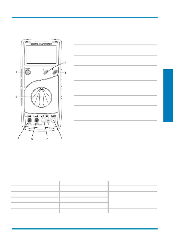
Switches, buttons and sockets description
(1) ON/OFF switch
The device is turned on and off using the "POWER"
push-button switch.
(2) Lighting switch (☼)
Press this button to turn the torch function on and off.
(3) Memory log button (H)
Press this button to store the actual measurement value.
(4) Measuring function selector switch
Use the rotary selector switch to select the various
measurement modes.
(5) 10 A socket (left)
The 10 A socket must be used for current measure-
ments above 200 mA.
(6) mA socket
For current measurements up to 200 mA.
(7) Input socket V/Ω/TEMP/CAP
Red test lead for all types of signals supported by the
instrument.
(8) Ground socket
Black test lead for all types of signals supported by the
instrument.
DC voltage measurement / V=
Use the selector switch to set the appropriate range. Insert the black test lead into the ‘COM’
socket and the red test lead into the V/Ω/TEMP/CAP socket. Using the test probes, touch the test
points of the test object. Read measurement value on the display. The polarity of the voltage will
also be displayed.
DC voltage
± 0.5 % of reading + 1 digits
± 0.5 % of reading + 3 digits
± 0.8 % of reading + 3 digits
- Input resistance: 10 MΩ
- Max. input voltage: 600 V DC
 Loading...