Conductance
EXPERIMENT
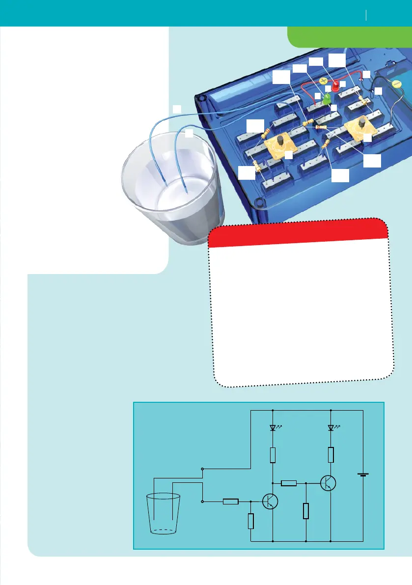
Humidity detector
YOU WILL NEED
resistors, Ω
resistor, . kΩ
resistor, kΩ
resistor, kΩ
resistor, kΩ
short wire bridges
long wire
connectors
LEDs
transistor modules
electronics board
battery clip
+ and additional household
items: 9-volt square battery,
glass of water
+
–
9V
T2
T1
R 5
3.3 kΩ
R 2
100 kΩ
R 6
470 Ω
R 4
22 kΩ
LED 2
LED 1
R 3
470 Ω
R 1
220 kΩ
A
B
HERE’S HOW
1. Assemble the circuit following the
circuit diagram. You will use the
loose ends of the two long wires
(“A” and “B”) as “sensors.”
2. Fill a glass with tap water.
3. Dangle the two long wires A and B
into the glass.
What happens?
4. Now pull the
wires back out of
the glass.
5. Hang the two
wires in the water
again and wait a
couple days.
What happens
when the water
evaporates?
As soon as the two long wires touch the
water, the green LED lights up — an
indication that there’s enough water
present. If you pull one of the wires out
of the glass, the green LED will go out
and the red one will come on. The same
thing happens, of course, when the
water level drops far enough in the glass
for the wires to be no longer covered
with water. The red LED turns on, in
other words, when there’s not enough
water!
WHAT’S HAPPENING?
R1
KΩ
R5
. KΩ
R4
KΩ
R6
Ω
LED2
LED1
T1
A
+
–
B
T2
A
C
A
C
R3
Ω
R2
KΩ