Alarm Systems
EXPERIMENT
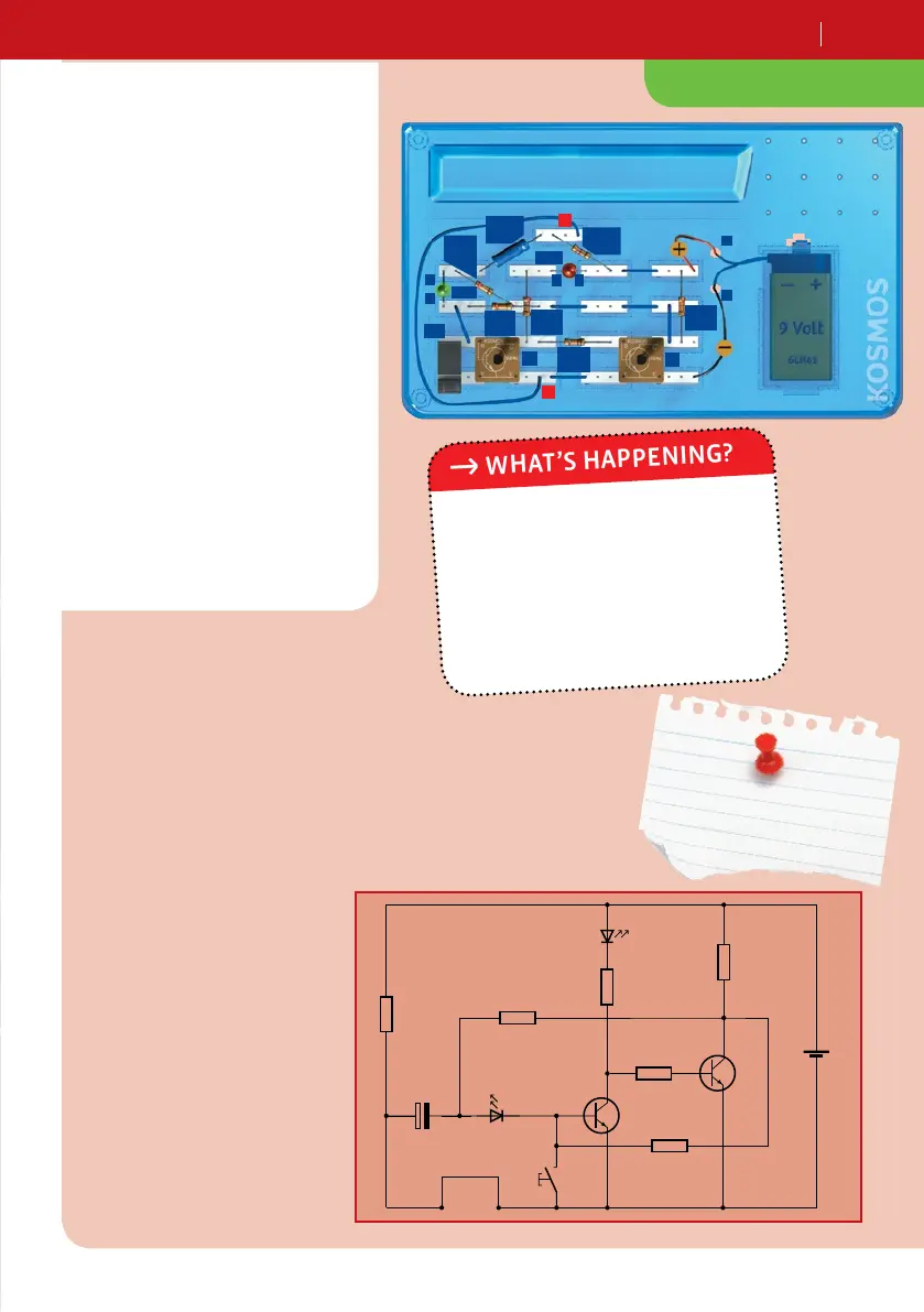
Alarm system
YOU WILL NEED
resistors, Ω
resistor, . kΩ
resistor, kΩ
resistor, kΩ
resistor, kΩ
capacitor µF
LEDs
transistor modules
pushbutton
short wire bridges
long wire connector
electronics board
battery clip
+ and additional household
item: 9-volt square battery
HERE’S HOW
1. Assemble your alarm system.
2. Connect the contact clips marked
“A” and “B” with a long wire.
3. When you hook up the battery and
push briefly on the pushbutton, the
red LED (LED2) goes out.
4. The alarm system is now
ready for you to test it by
pulling the long wire out of
the circuit.
As soon as the connection
between the A and B contact
clips is interrupted, the red LED
turns on: Alarm! And the green
LED only comes on briefly when
the alarm is shut off.
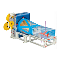
WHAT’S HAPPENING?
+
–
9V
T2
T1
R 1
470 Ω
R 2
470 Ω
R 5
3.3 kΩ
R 3
100 kΩ
R 6
220 kΩ
R 4
22 kΩ
+
10 µF
C 1
Ta 1
LED 2
LED 1
Tip
Continue right away to
the next experiment.
LED1
LED2
T1
Pb1
+
–
T2
A
A C
C
R1
Ω
C1
µF
R
. kΩ
R
kΩ
R
kΩ
R
Ω
R
kΩ
A
B
+