Timer Switches
EXPERIMENT
Timer switch
YOU WILL NEED
resistors, Ω
resistor, . kΩ
resistor, kΩ
resistor, kΩ
resistor, kΩ
capacitor µF
LEDs
transistor modules
pushbutton
short wire bridges
long wire bridge
electronics board
battery clip
and additional household
item: 9-volt square battery
HERE’S HOW
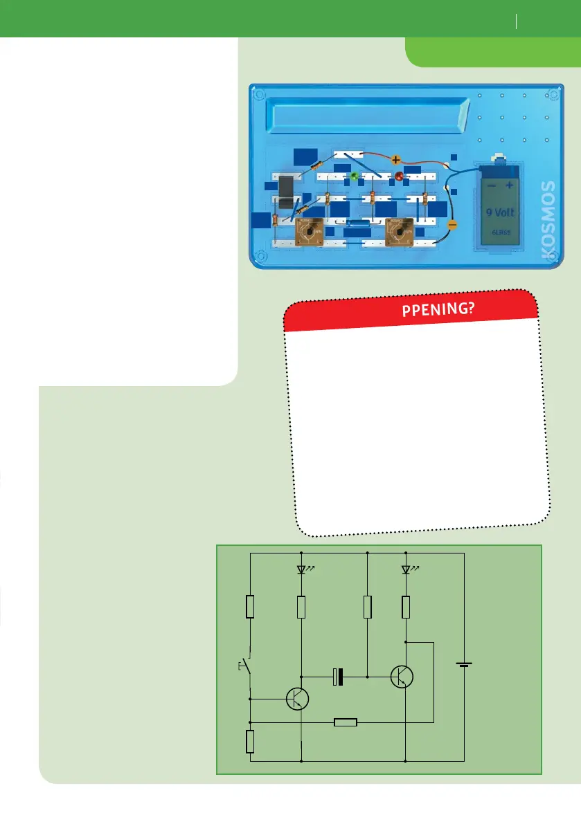
1. Assemble your timer switch and
connect the battery. Wait for the
red LED to come on and the green
one to go out by itself. Now your
timer switch is ready!
2. Press once on the
pushbutton.
When you first connect the battery, the
green LED is lit up while the red one is
switched off. Your timer switch is ready
once the red LED comes on by itself and
the green one goes out.
As soon as you press the pushbutton, the
green LED comes on and the red one goes
out. After a cycle time of just under a
second, the timer switch returns to its
starting state. The cycle time is deter-
mined by capacitor C1 and resistor R5.
WHAT’S HAPPENING?
+
–
9V
T2
T1
R 2
22 kΩ
R 1
3.3 kΩ
R 5
220 kΩ
R 3
470 Ω
R 4
100 kΩ
+
10 µF
C 1
Ta 1
LED 1
R 6
470 Ω
LED 2
LED1
LED2
T1
Pb1
+
–
T2
A AC
+
C
R1
. kΩ
R
Ω
C1 µF
R
kΩ
R
Ω
R
kΩ
R4
kΩ