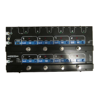
1. Strong metal Lid (lid and tray construction)
2. Foot switch (8 strong foot or hand operated switches)
3. Control mini switches (6 mini switches) Replaceable.)
4. Effects loops mini switches (4 mini switches) Replaceable.)
5. Phase Switch (Reverses phase of out 2)
6. Output 2 (isolated) (Jack Socket)
7. Expand out/in (For use with two or more GigRigs)
8. Output 1 (Main amp) (Jack Socket)
9. 9V input (use TheGigRig Pro-8 supply only)
10. Box base (steel tray base)
11. Output 1 LED indicator (on when output is live)
12. Post volume level indicator (Brightness shows volume setting)
13. Post volume on indicator (on when post amp is in the signal path)
14. Remote switch 1 LED (normally closed when LED is off)
15. snd and rtn for effects pedals (6 separate loops at back of unit.)
16. Mode toggle switch (single or multi patch for top rail)
17. Effects loop LED (on when effect is in the signal path)
18. Pre-set LED (on when patch is selected)
19. Post volume control (Volume control for each patch)
20. Top reinforced switch rail (Strong Chrome rail for stomping on)
21. Midi option available (MIDI output Option, Not fitted)
22. Guitar input (on side) (Input from guitar or other instruments)
23. 9V output (on side) (Used to power all your 9V pedals etc.)