DIAGRAM 3
YOUR TRICYCLE COMES PARTIALLY ASSEMBLED AND IF BOXED
REQUIRES ONE OR MORE OF THE FOLLOWING STEPS.
1. Carefully remove the polythene wrapping using a sharp knife and
any other packaging material. Care should be taken not to damage
the upholstery, tyres and paintwork.
2. The tricycle mainframe is split into two parts; the Mainframe Unit
and the Rear Unit (see Diagram 2). To assemble these parts first
remove the M8 cap screw from the Mainframe Unit using the allen
wrench provided and then slide this fully into the Rear Unit. Refit the
M8 cap screw but do not tighten anything at this stage.
* We recommend that before attempting the next stages you protect
your clothes and floorcovering as this part contain grease*
3. CHAIN: To fit the chain, place it onto the front chainring and then
fit it onto the rear cog. If you are unable to fit the chain fully onto the
rear cog then place as much chain onto the teeth of the cog as
possible and then turn the rear drive wheel (rear left) which will feed
the chain onto the cog.
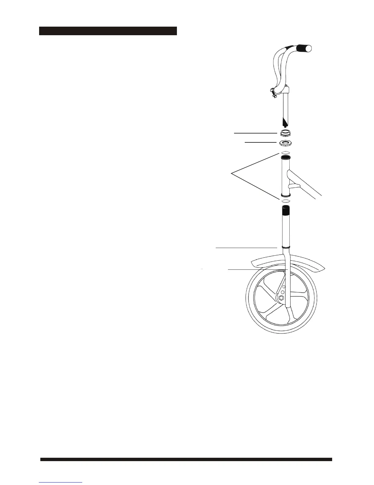
4A. ATTACHING FRONT WHEEL/FORK TO REAR OF TRIKE (IMP
AND TERRIER MODELS ONLY) (See Diagram 3): To attach front
wheel and fork to the rear of tricycle, first remove the two lock nuts
at the top of the threaded steering column. Leave one set of ball
bearings at the base of the steering column. Insert front wheel and
fork upwards into front of tricycle. Fit the other set of ball bearings
over the steering column with the ball bearings facing downwards and
replace locknuts on the threaded column, the broad flat lock nut first,
followed by the spacer washer (if fitted) and the smaller lock nut.
Tighten until the steering can be turned easily. Overtightening will
make the steering stiff.
4B. ATTACHING FRONT WHEEL/FORK TO REAR OF TRIKE
(FRAME FOLDING MODELS ONLY): The frame folding mechanism
enables the Tricycle to be split into 2 parts for storage and
transportation. To join the parts together, remove the black knob and
washer from the front section and the black knob with the threaded
stud and washer from the rear section. Bring both halves together and
reattach the black knobs.
5. HANDLEBARS: Fit the Handlebars and stem into the Steering
Column and secure with the Allen key bolt at the top of the Handlebar
Stem. Swing the Handlebars into desired position and secure with the
Allen key bolt on the underside of the Handlebar Stem. The
Handlebars are height adjustable. HINT: Loosen the bolt and then tap
the bolt head, this will dislodge the locking mechanism, then secure
tightly in place.
6. CHAIN TENSION (See Diagram 2): To tension the chain, pull the
Rear Unit back whilst holding the Mainframe Unit, this will effectively
stretch the chain. Tighten the M8 Frame Cap Screw with the allen
wrench and then securely tighten the M12 Frame Stud Nuts with a 3/4
or 19MM wrench. Turn the pedal to ensure that the chain is running
smoothly. The chain tension is correct when the chain has 1/4” of slack
in the middle.
7. CHAIN GUARD: The plastic chainguard is pre-drilled and should be
fixed to the trike using the self tapping screws which will be attached to
the frame.
ASSEMBLY
Small lock nut
Broad flat lock nut
Ball Bearings
Collar
Front Fork
 Loading...