Manual 0-2582 23 SERVICE TROUBLESHOOTING
If Input Bridge Diode is shorted, make the following
checks with an ohmmeter at the Main Contactor:
Meter (+) Meter (-) Indication
L1 T1 Open
L2 T2 Open
L3 T3 Open
If any test has resistance, then replace the Main Contac-
tor also.
E. Main Contactor (MC1) Test
Reconnect power and observe proper start-up procedure.
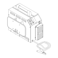
Indicator D34 on the Logic PC Board should be ON. If
indicator D34 is OFF there is no voltage to the Power
Supply or an overvoltage condition exists.
A-01409
Logic PC Board
D34
If indicator D34 is OFF check for proper AC input volt-
age per the following:
• Single Phase Units check at L1 and L2
• Three Phase Units check L1, L2, and L3
L1
L2
L3
Main Contactor
(MC1)
A-01195
Coil
Wire #59
Coil
Wire #55
Measure voltage on coil of contactor, approximately 117
VAC between wires #55 and #59.
• If voltage is correct, replace Main Contactor.
• If voltage is incorrect, replace Logic PC Board.
F. Temperature Circuit Test
Test the temperature circuit per the following:
1. Place the front panel ON/OFF switch to the OFF
position.
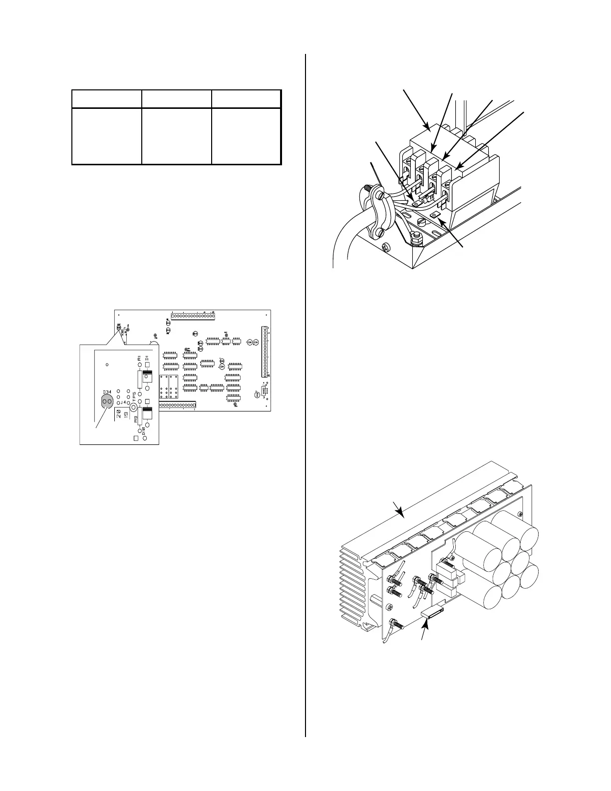
2. Disconnect ribbon cable from the Upper FET/
Heatsink Assembly at J6.
A-01410
J6
FET/Heatsink and
Capacitor PC Board
Assembly
3. Place the front panel ON/OFF switch to ON.
4. Check status of the TEMP indicator. If indicator
has gone OFF, then remove power and replace the
Upper FET/Heatsink Assembly.
5. Place the front panel ON/OFF switch to the OFF
position.
 Loading...


