Manual 0-2582 25 SERVICE TROUBLESHOOTING
A-01412
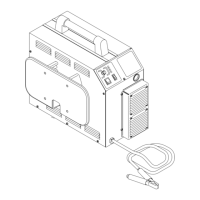
Logic PC
Board
D34
D5
D15
D31
D35
D33
Indicator Meaning
D5
Torch Switch Enable - When ON
indicates torch switch is pressed.
D15
CD Enable - Initiates spark gap on
CD PC Board. Indicator should
come ON then go OFF after a pilot
arc has been established.
D31
CSR - Indicates main cutting arc is
established.
D33
Pilot ON - Indicates that a true pilot
arc has started. OFF during cutting.
D34
AC OK - When ON indicates that AC
Input voltage is okay.
D35
Drag On - When ON indicates that
the torch tip is making contact with
the workpiece.
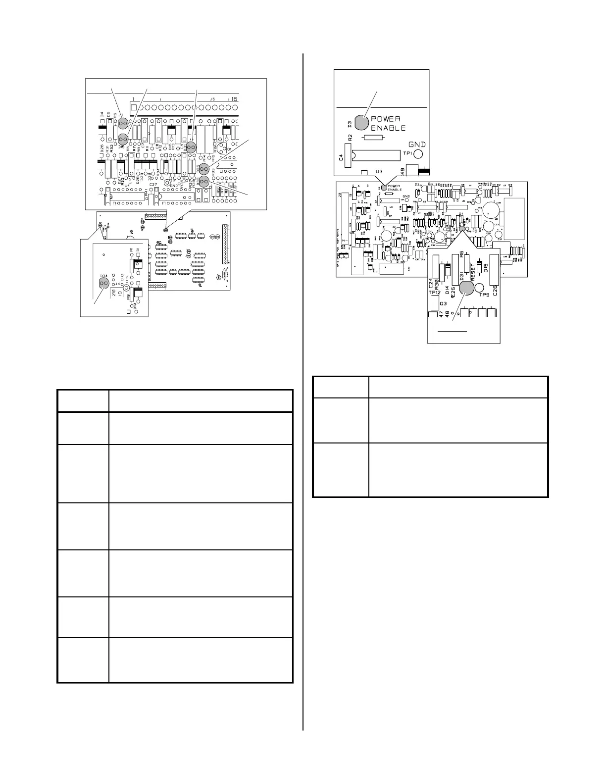
The indicators on the Gate Drive PC Board as follows:
Gate Driver PC Board
A-01200
D34
RESET
D3
POWER ENABLE
Indicator Meaning
D3
Power Enable - When ON PWM
Enable received from the Logic
PC Board.
D31
Reset - Indicator will blink if
primary over-current is detected
when torch switch is pressed.
1. No DC Output
An open circuit voltage of approximately 280 to 325
VDC (depending on input power selected) is pro-
duced when switching transistors in the FET/
Heatsink Assemblies are turned ON by a PWM En-
able signal from the Logic PC Board. A circuit on the
Logic PC Board monitors the output voltage. When
the output voltage drops below 60 VDC, indicating a
problem exists, the Logic PC Board sends a signal
which turns OFF the PWM Enable signal to the Gate
Drive PC Board. Because this happens in less than 50
milliseconds, it is not easy to take voltage readings to
find the source of the problem.
When the unit is at “idle” the AC OK indicator, D34,
should be ON. The Torch Switch Enable indicator,
D5, turns ON when the torch switch is pressed. At
this point the gas begins to flow. When the preflow
 Loading...


