108
106308-05 - 3/23
APEX Installation, Operating, & Service Instructions
M. Energy Management System (EMS) Interface
The control system has a fully featured ability to interface with an Energy Management System (EMS). The
control system allows remote control and monitoring via RS485 Modbus or through direct wiring. The following
sections outline setup of the EMS interface and adjustable EMS interface parameters. Select Main Menu >> EMS
to access EMS parameters.
1. Setup
Complete steps shown in Table 10-25 to set up a multiple boiler system with EMS interface.
Table 10-25: Energy Management System Setup Procedure
Step Description Comments
1
Install Ethernet
cables between
boilers
See Figure 8-9. Use standard Ethernet type cables to make connection between boilers. Alternatively, terminal
screws A, B, and C labeled Boiler-to-Boiler may be used.
NOTE: The same Ethernet cable that connects the Boiler-To-Boiler Sequence Master also connects the EMS
Modbus signals.
2
Enable EMS
communication
Select Main Menu >> EMS >> Modbus Setup >> EMS Enable/Disable >> Enable.
3
Set unique
Modbus
addresses
“Comm HMI
Station”
SEE MODBUS SETUP PARAMETERS BEFORE PROCEEDING
Program COM2 only
The EMS Modbus address may be independent to the Boiler number or boiler address. Select Main Menu >>
EMS >> Modbus Setup >> EMS Modbus Parameters. Follow on screen instructions.
NOTE: Each boiler must have a unique Comm HMI Station address.
4
Adjust
communication
parameters
Communication parameters are adjustable. Select Main Menu >> EMS >> Modbus Setup >> EMS Modbus
Parameters. Follow on screen instructions.
NOTE: Baud Rate and Parity must match the EMS settings for communication to be established.
5
Confirm
communication
The display provides a list of all EMS signals. Select Main Menu >> EMS >> Points List. Use the list to verify
signals sent and received from the EMS.
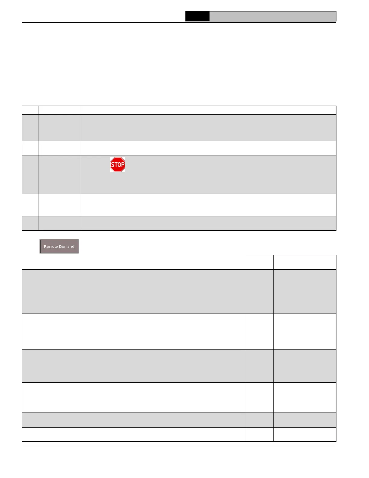
2. Remote Demand Parameters
Select to access the following parameters.
Parameter and Description
Factory
Setting
Range / Choices
Modulation Source
The boiler can modulate (vary boiler heat input) based on local or remote (4-20 mA or Modbus)
signals. Modulation begins after the start sequence finishes and the boiler is released to modulate.
Modulation Source has the following selections:
Local Local setpoint and control is used to create firing rate.
4-20mA Input wired to Remote 4-20 mA terminals is used as modulation rate.
Modbus Modbus signal is used as modulation rate.
Local
Local,
4-20 mA,
Modbus
Central Heat Setpoint Source & Lead Lag Setpoint Source
The setpoint may be based on local (customer entered value or outdoor reset) or remote (4-20mA or
Modbus) signals. Setpoint Source has the following selections:
Local Local setpoint and control is used to create firing rate.
4-20mA Input wired to Remote 4-20 mA terminals is used as modulation rate.
Modbus Modbus signal is used as modulation rate.
Local
Local,
4-20 mA,
Modbus
CH Demand Switch
The Central Heat demand (Enable Disable) can be directly wired to the boiler or provided by the
Modbus interface. Ignored when boiler is controlled by sequencer.
Local Enable Disable terminals provide demand.
Modbus Modbus signal provides demand.
Local
Local,
Modbus
LL Demand Switch
The Sequencer Master’s demand (Enable Disable) can be directly wired to the boiler or provided by
the Modbus interface. Used only on Sequencer Master boiler.
Local Enable Disable terminals provide demand
Modbus Modbus signal provides demand.
Local
Local,
Modbus
4-20 mA Water Temp
Sets the Central Heat Setpoint temperature corresponding to 4 mA.
130°F
(54.4°C)
50°F (10°C) -
Central Heat Setpoint
20 mA Water Temp
Sets the Central Heat Setpoint temperature corresponding to 20 mA.
180°F
(82.2°C)
50°F (10°C) -
Central Heat Setpoint
10 Operation (continued)
 Loading...