24
106308-05 - 3/23
APEX Installation, Operating, & Service Instructions
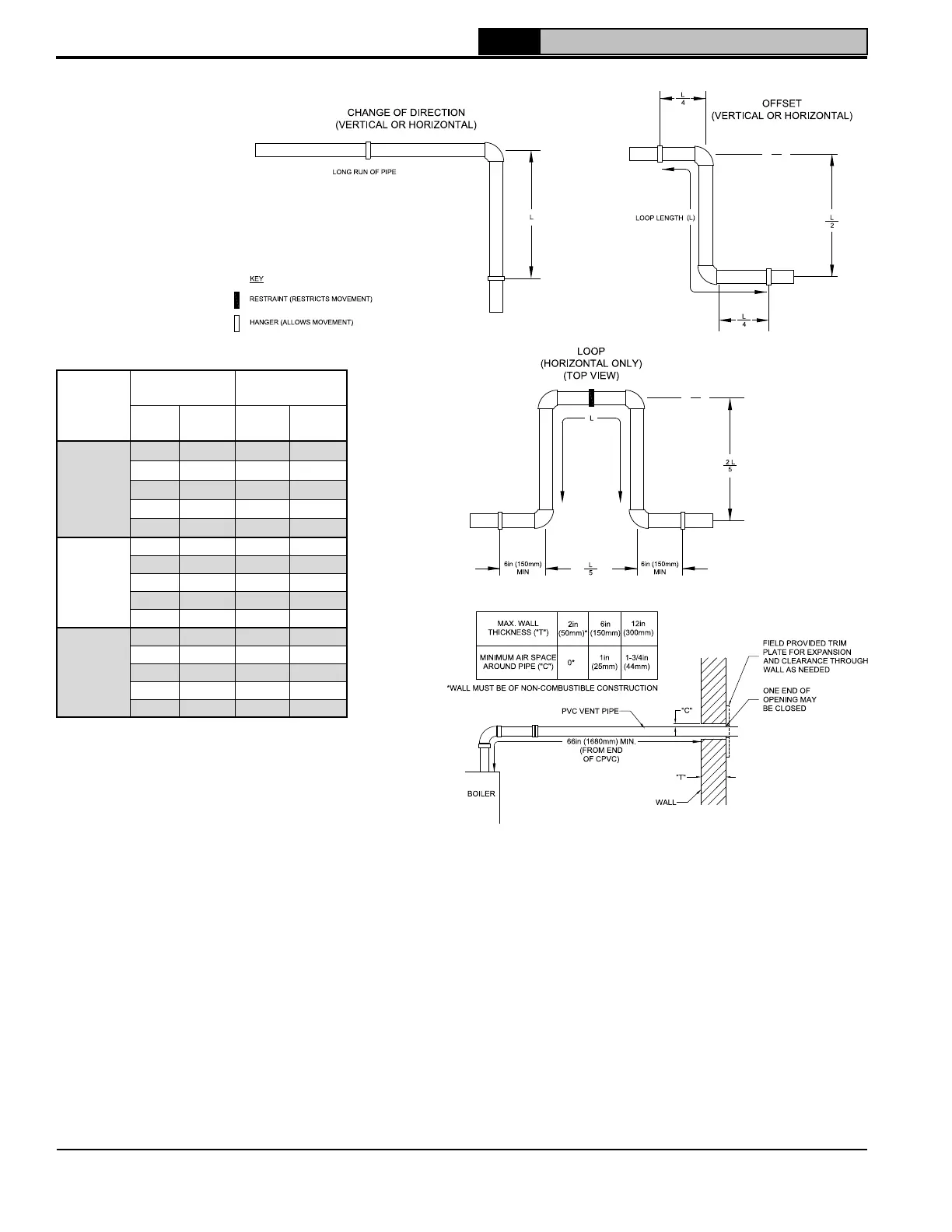
Figure 4-18: CPVC/PVC Expansion Loop and Offset
Table 4-17: Expansion Loop Lengths
Nominal
Pipe
Dia. (In.)
Length of
Straight Run
Loop Length
“ L”
ft. m in. mm
3
20
6.1
53
1350
30
9.1
65
1650
40
12
75
1900
50
15
84
2130
60
18
92
2340
4
20 6.1 60 1520
30 9.1 74 1880
40 12 85 2159
50 15 95 2413
60 18 104 2642
6
20 6.1 73 1850
30 9.1 90 2290
40 12 103 2620
50 15 116 2950
60 18 127 3230
Figure 4-19: Wall Penetration Clearances
for PVC Vent Pipe
• PVC vent pipe may not be used
to penetrate combustible or non-
combustible walls unless all
following three conditions are met
simultaneously (see Figure 4-19):
- The wall penetration is at least 66
in. (1680 mm) from the boiler as
measured along the vent
- The wall is 12 in. (300 mm) thick
or less
- An air space of at least of that
shown in Figure 4-19 is maintained
around outside of the vent pipe to
provide air circulation
• If above three conditions cannot be
met simultaneously when penetrating
a combustible wall, use CPVC pipe
for wall penetration.
• Size and cut wall opening such that
a minimal clearance is obtained and
to allow easy insertion of vent pipe.
Wall thimbles for CPVC/PVC pipe
are available from Thermal Solutions:
P/N’s 102180-01 (3 in.), 102181-01 (4
in.), 103419-01(6 in.).
• Apply sealant between vent pipe and
wall opening to provide weather-tight
seal. Sealant should not restrain the
expansion of the vent pipe.
• Install contractor provided optional
trim plate on wall outside surface to
cover wall opening (see Figure 4-19).
• Secure trim plate to wall with nails or
screws and seal ID and plate OD or
perimeter with sealant material.
4 Venting (continued)
 Loading...