53
106308-05 - 3/23
APEX Installation, Operating, & Service Instructions APEX Installation, Operating, & Service Instructions
Figure 6-16, continued: Multiple Boiler Water Piping w/Domestic Hot Water Heater (Page 2 of 2)
WARNING
Explosion Hazard.
Failure to properly pipe gas supply to boiler may
result in improper operation and damage to the
boiler or structure. Always assure gas piping is
absolutely leak free and of the proper size and
type for the connected load.
An additional gas pressure regulator may be
needed. Consult gas supplier.
NOTICE: Size corrugated stainless steel tubing
(CSST) to ensure proper capacity and minimize
flow restrictions.
A. Size gas piping. Design system to
provide adequate gas supply to boiler.
Consider these factors:
1. Allowable pressure drop from point of delivery
to boiler. Maximum allowable system pressure
is ½ psig (3.4 kPa). Actual point of delivery
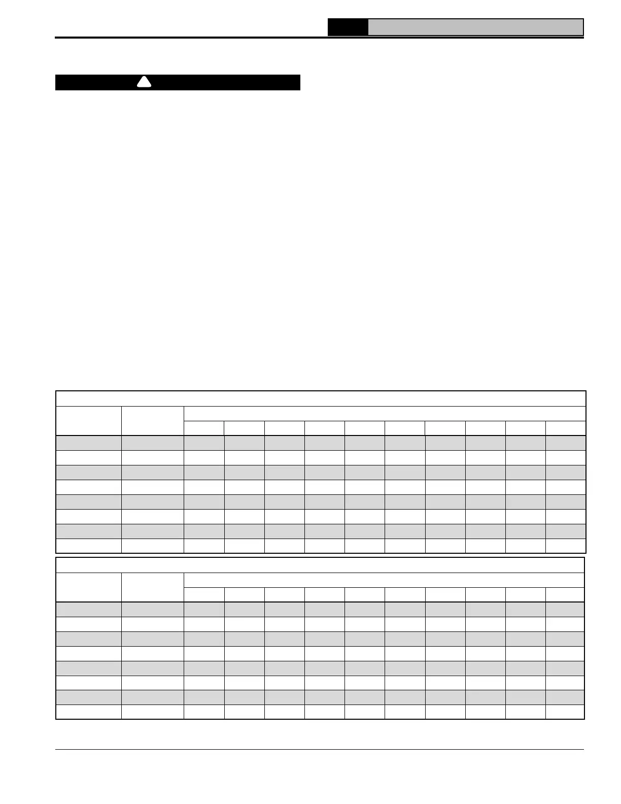
Table 7-1: Maximum Capacity of Schedule 40 Black Pipe in CFH* (Natural Gas) For Gas Pressures of 1/2 psi
(3.4 kPa) or Less
pressure may be less; contact gas supplier for
additional information. Minimum gas valve inlet
pressure is printed on the rating label located
in the boiler’s vestibule compartment.
2. Maximum gas demand. Refer to the boiler’s
input as printed on its rating label. Also
consider existing and expected future gas
utilization equipment (i.e. water heater, cooking
equipment).
3. Length of piping and number of fittings. Refer
to Tables 7-1 (natural gas) or 30 (LP gas) for
maximum capacity of Schedule 40 pipe. Table
7-3 lists equivalent pipe length for standard
fittings.
4. Specific gravity of gas. Gas piping systems for
gas with a specific gravity of 0.60 can be sized
directly from Table 7-1 and gas with a specific
gravity of 1.5 can be sized from Table 7-2,
unless authority having jurisdiction specifies
a gravity factor be applied. For other specific
gravity, apply gravity factor from Table 7-4. If
exact specific gravity is not shown choose next
higher value.
Inlet Pressure 14.0 in wc (3.4 kPa)or less; 0.5 in wc (0.12 kPa) Pressure Drop
Nominal
Pipe Size, In.
Inside
Diameter, In.
Length of Pipe, ft.
10 20 30 40 50 60 70 80 90 100
½ 0.622 172 118 95 81 72 65 60 56 52 50
¾ 0.824 360 247 199 170 151 137 126 117 110 104
1 1.049 678 466 374 320 284 257 237 220 207 195
1¼ 1.380 1390 957 768 657 583 528 486 452 424 400
1½ 1.610 2090 1430 1150 985 873 791 728 677 635 600
2 2.067 4020 2760 2220 1900 1680 1520 1400 1300 1220 1160
2½ 2.469 6400 4400 3530 3020 2680 2430 2230 2080 1950 1840
3 3.068 11300 7780 6250 5350 4740 4290 3950 3674 3450 3260
* 1 CFH of Natural Gas is approximately equal to 1 MBH; contact your gas supplier for the actual heating value of your gas.
Inlet Pressure 14.0 in wc (3.4 kPa)or less; 0.3 in wc (0.07 kPa) Pressure Drop
Nominal
Pipe Size, In.
Inside
Diameter, In.
Length of Pipe, Ft.
10 20 30 40 50 60 70 80 90 100
½ 0.622 131 90 72 62 55 50 46 42 40 38
¾ 0.824 273 188 151 129 114 104 95 89 83 79
1 1.049 514 353 284 243 215 195 179 167 157 148
1¼ 1.380 1060 726 583 499 442 400 368 343 322 304
1½ 1.610 1580 1090 873 747 662 600 552 514 482 455
2 2.067 3050 2090 1680 1440 1280 1160 1060 989 928 877
2½ 2.469 4860 3340 2680 2290 2030 1840 1690 1580 1480 1400
3 3.068 8580 5900 4740 4050 3590 3260 3000 2790 2610 2470
7 Gas Piping
!
 Loading...