60
106308-05 - 3/23
APEX Installation, Operating, & Service Instructions
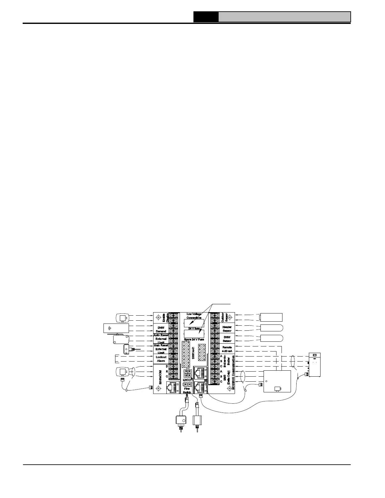
Figure 8-4: Low Voltage Field Wiring
OR
SIZE 399-525: 1.6A SLOW BLOW
SIZE 600-825: 2.0A FAST ACTING
5mm X 20mm FUSE
OR
(+)
(-)
SPACE HEATING
THERMOSTAT
OPTIONAL
DOMESTIC HOT WATER
THERMOSTAT (IF USED)
DAMPER PROVING
SWITCH (IF USING
ROOM AIR)
OPTIONAL MANUAL RESET
EXTERNAL LIMIT(S)
ALARM CONTACTS
OPTIONAL ENVIRACOM
THERMOSTAT OR
ZONE PANEL
FLOW
SWITCH
OPTIONAL
OPTIONAL
OUTDOOR
SENSOR
OPTIONAL
HEADER SENSOR
OPTIONAL
DOMESTIC HOT
WATER SENSOR
OPTIONAL
MULTIPLE BOILER
COMMUNICATION
OPTIONAL
ENERGY
MANAGEMENT
SYSTEM
OR
OR
OPTIONAL AUTO
RESET EXTERNAL
LIMIT(S)
3. 24 VAC low voltage connections are located on
left side of right PCB and are shown in Figure
8-4. One 24V fuse and spare are provided.
APX425C and APX525C use 1.6A slow-blow
fuse. APX625C, APX725C and APX825C use
2.0A fast-acting fuse.
4. 5VDC low voltage connections are located on
right side of right PCB and are shown in Figure
8-3.
5. If the outdoor sensor is connected, the boiler
will adjust the target space heating set point
supply water temperature downwards as the
outdoor air temperature increases. If used,
this sensor should be located on the outside
of the structure in an area where it will sense
the average air temperature around the house.
Avoid placing this sensor in areas where it may
be covered with ice or snow. Locations where
the sensor will pick up direct radiation from
the sun should also be avoided. Avoid placing
the sensor near potential sources of electrical
noise such as transformers, power lines, and
fluorescent lighting. Wire the sensor to the
boiler using 22 gauge or larger wire. As with
the sensor, the sensor wiring should be routed
away from sources of electrical noise. Where it
is impossible to avoid such noise sources, wire
the sensor using a 2 conductor, UL Type CM,
AWM Style 2092, 300 Volt 60°C shielded cable.
Connect one end of the shielding on this cable
to ground.
NOTICE: When making low voltage connections,
make sure that no external power source is
present in the thermostat or limit circuits. If such
a power source is present, it could destroy the
boiler’s microprocessor control. One example
of an external power source that could be
inadvertently connected to the low voltage
connections is a transformer in old thermostat
wiring.
E. Flow Switch Wiring
Apex boilers require a flow switch to prevent boiler
overheating. See Section 6 “Water Piping and Trim”,
and flow switch instruction sheet for piping details.
The flow switch and flow switch wire harness are
factory provided.
1. Wire flow switch harness to boiler. Connect
Molex on harness to boiler low voltage
connector P11, labeled “Flow Switch”.
2. Wire flow switch harness to flow switch.
Connect fork terminals on harness to flow
switch NO (normally open) and COM
(common) terminal screws.
8 Electrical (continued)
 Loading...