80
106308-05 - 3/23
APEX Installation, Operating, & Service Instructions
9. Central Heating System Frost Protection
When enabled, Frost Protection starts the
boiler and system pump and fires the boiler
when low outside air and low supply water
temperatures are sensed. The Control
provides the following control action when frost
protection is enabled:
Table 10-5: Frost Protection
Device
Started
Start
Temperatures
Stop
Temperatures
Boiler
Pump
Outside Air < 0°F ° (-18°C)
or Supply Water < 45°F (7.2°C)
Outside Air > 4°F (-16°C)
or Supply Water > 50°F (10°C)
Boiler Supply Water < 38°F (3.3°C) Supply Water > 50°F (10°C)
FROST PROTECTION NOTE
The Control helps provide freeze protection for the boiler
water. Boiler flue gas condensate drain is not protected
from freezing. Since the Control only controls the system
and boiler circulators individual zones are not protected.
It is recommended that the boiler be installed in a location
that is not exposed to freezing temperatures.
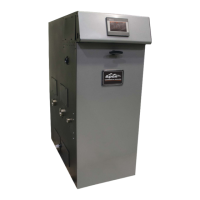
E. Touch Screen Display Navigation
1. HOME SCREEN is the default state for the display, shown in Figure 10-3. The home screen displays basic
operating information and provides access to other screens through icons at the top of the screen.
Figure 10-3: Home Screen
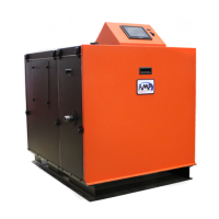
Limit String
Type
Description Action
STAT Heat Demand
“ON” indicates heat demand and enables control to fire to maintain water temperature at setpoint.
• Heat demand may be received from “Enable/Disable” terminals for Central Heat Demand, “DHW Demand”
terminals for DHW Demand, the Sequencer Master, or EMS Modbus inputs.
• Heat Demand input “ON” initiates pump and combustion air damper outputs.
A1 Annunciator 1
A1 is the air proving switch and must cycle “ON” and “OFF” at appropriate times in order for boiler to start.
• A1 must prove “OFF” before blower starts. A1 “ON” before blower starts causes manual reset hard lockout
after a delay.
• A1 must prove “ON” after blower starts and before trial for ignition. A1 “OFF” during this time causes
manual reset hard lockout after a delay.
A2/LCI
Annunciator 2/
Load Control
Input
A2 limits are upstream of and connected in series with LCI limits. LCI must prove “ON” for boiler to start.
Boiler will shut down if LCI is turned “OFF” during operation.
• Hold message shown when LCI limit is “OFF” and Heat Demand is “ON”.
• LCI Hold will never cause a manual reset lockout.
• Boiler may be disabled remotely by wiring an enable contact to the LCI “External Limit” terminals.
ILK Interlock
ILK must prove “ON” for boiler to start. Boiler will shut down with manual reset hard lockout if ILK is turned
“OFF” during operation. ILK OFF Lockout closes the Lockout Alarm contacts.
Table 10-4: Limit String
10 Operation (continued)
Figure 10-2: Limit String Status Screen Showing
Central Heat Demand
 Loading...