82
106308-05 - 3/23
APEX Installation, Operating, & Service Instructions
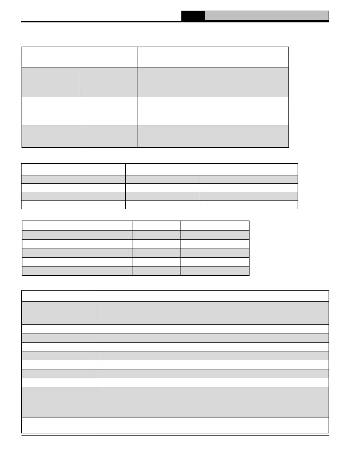
Table 10-8: Hydronic System
Parameter and
Description
Factory Setting Range/Choices
Boiler Pump Any Demand
Never, Any Demand
Central Heat, OFF DHW Demand
Header Sensor Demand/
Combustion air Damper
System Pump Any Demand
Never
Any Demand
Central Heat, No Priority
Central Heat, Optional Priority, Fresh Air Damper
DHW Pump
Primary Loop Piped
IWH
Never
Primary Loop Piped IWH
Boiler Piped IWH, Fresh Air Damper
Table 10-9: Comfort Settings
Parameter and Description Factory/Setting (°F) Range/Choices (°F)
Minimum Outdoor Temperature 0 -50 to 32
Maximum Outdoor Temperature 70 35 to 100
Low Water Temperature 110 70 to 180
Minimum Boiler Water Temperature 130 50 to 185
Parameter and Description Factory Setting Range / Choices
Central Heat Response Speed 3 1 to 5
Central Heat Low Fire Hold Time 120 seconds 0 to 1800 seconds
Domestic Response Speed 3 1 to 5
Domestic Low Fire Hold Time 10 seconds 0 to 1800 seconds
Sequencer Response Speed 3 0 to 5
Table 10-10: Response Speed
Status Description
Standby
Boiler is not firing. Appropriate circulators are on if Priority is not Standby. With a
central heat demand, sequence proceeds from Standby when supply temperature
drops below Setpoint minus Difference Below.
Safe Startup Flame circuit is tested.
Drive Purge Blower is driven to purge speed.
Prepurge Combustion chamber is purged for 10 s after reaching purge speed.
Drive Lightoff Blower is driven to lightoff speed.
Preignition Test Control conducts safety relay test.
Preignition Spark is energized and it is confirmed that no flame is present.
Direct Ignition Spark and gas valve are energized.
Running
After flame is proven, sequence continues with run stabilization and, when selected,
low fire hold time and slow start ramp. Once field adjustable low fire hold time
and ramp rate is completed, normal boiler operation begins with modulation rate
dependent on temperature and setpoint selections.
Postpurge
When the call for heat ends, gas valve is closed. Combustion chamber is purged for
10 s after blower reaches postpurge speed.
Table 10-11: Sequence of Operation
10 Operation (continued)
 Loading...