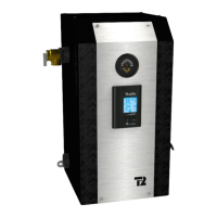
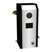
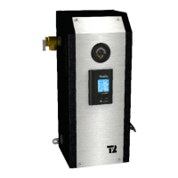
EasyManua.ls Logo

THERMO 2000 BTH ULTRA 12 User Manual

THERMO 2000 BTH ULTRA 12
29 pages
To Next Page IconTo Next Page
Page #1 background imageLoading...
Page #1 background image
Electric Boilers
BTH ULTRA
Models ranging from 12 kW to 36 kW 208/240 Volts (1 phase)
INSTALLATION & OPERATION MANUAL
THERMO 2000 INC. Revision : June 2015
Printed In Canada
Your BTH ULTRA Electric Boiler has been carefully assembled and factory tested to provide
years of trouble-free service. The following information and safety measures are provided to
enable proper installation, operation, and maintenance of this product.
It is imperative that all persons who are expected to install, operate or adjust this boiler should
read these instructions carefully.
Any questions regarding the operation, maintenance, service or warranty of this electric boiler
should be directed to the supplier.
When all installation steps have been completed, keep this installation manual in a safe place
(close to the boiler) for future reference.

Table of Contents

Questions and Answers:

THERMO 2000 BTH ULTRA 12 Specifications

General IconGeneral
BrandTHERMO 2000
ModelBTH ULTRA 12
CategoryBoiler
LanguageEnglish

Summary

Technical Specifications

General Safety Precautions

Introduction

Provides an overview of safeguards and instructions for safe operation, emphasizing common sense.

Local Installation Regulations

Boiler must be installed according to instructions and local/national codes.

Corrosive Environment

Boiler should not be installed near corrosive atmosphere or high humidity.

Inspection Upon Reception

Inspect boiler for shipping damage; file claims with carrier.

To Be Checked

Check identification tag for model, voltage, phase, and ASME construction.

Installation

Safety Measures

Details on pressure relief valve, operating range, heat transfer solution, and high limit controls.

Location

Specifies clean, dry location, protection from freezing, mounting options, and ventilation.

Clearances

Minimum clearances required for inspection and servicing around the boiler.

Piping Installation

Type of installation

Introduces piping arrangements for self-operating and dual-energy units.

Boiler Piping Connection

Connect accessories and piping according to figures and mounting position.

Pressure Relief Valve

Installation of the supplied pressure relief valve and discharge piping.

Expansion Tank

Purpose and requirements for the expansion tank to store water volume changes.

Water Pressure Regulator

How to automatically feed water and prevent backflow with check valves.

Air Eliminator

Importance of air vents for removing air from the boiler and distribution system.

Circulating Pump

Selection and requirements for the circulating pump based on flow rate and temperature drop.

Drain Valve

Location and purpose of the drain valve for draining the unit.

Strainer

When a strainer might be required to prevent sediment damage.

Dual Energy Piping

Piping connections for dual-energy systems, parallel or series.

Electric Connections

Main Electric Supply

Boiler wiring, grounding, wire gauge, and breaker requirements per NEC.

120VAC Supply for External Accessories

Describes wiring for models 12-24 kW and 27-29 kW with 120VAC accessories.

No 120Vac Supply for External Accessories

Describes electrical supply without neutral for external accessories.

External Accessories Power Supply

Specifies limits for 120VAC and 24VAC external accessory consumption.

Outdoor Temperature Sensor

How to connect and use the outdoor sensor for temperature modulation.

Connecting Thermostat and Pump

Connects room thermostat and circulating pump, types of thermostats and wiring.

Zoning with Multiple Pumps

How to connect components for zoning systems with multiple pumps using relays.

Zoning with Motorized Valves

Connecting motorized zone valves, circulator, and thermostats.

Dual-Energy Connection with Auxiliary Boiler

How to connect the BTH ULTRA boiler for dual-energy operation.

Adjustment of the Controller

Introduction

Boiler is designed for closed circuit applications with two operation modes.

Displayed Information

Explains the LCD display and its icons for system operation visualization.

Operation of the Interface

Describes the controller's buttons for navigation, selection, and display illumination.

Operation in Fixed Boiler Temperature Set Point

How the boiler operates at a fixed target temperature without outdoor sensor.

Operation with Outdoor Reset

How the boiler modulates target temperature based on outdoor temperature.

Purge Delay of the Pump

Allows setting a delay for the pump after heat demand is completed.

Automatic Heating Shut Down

Option to automatically stop the boiler based on outdoor temperature.

Configuration of the Controller

Setting up the controller for dual-energy or electric-only modes before applying voltage.

Adjustments of Target Temperature by the User

How users can adjust the target temperature offset without entering configuration menus.

Boost System Operation

Explains the Boost feature for increasing target temperature under high heat demand.

Operation in Dual-Energy

Details how the controller indicates and operates in dual-energy or electric-only modes.

Start Up Operation

Preparatory Step

Checklist of tasks before powering on the boiler, including filling and checks.

Startup & Inspection

Steps for initial startup, monitoring element activation, and temperature increase.

Complementary Checks on Dual-Energy Installations

Verifying dual-energy operation, signal simulation, and auxiliary boiler checks.

Maintenance

Introduction

Recommends a routine maintenance program for dependable service.

At All Times

Immediate inspections for odors or leaks, and handling of safety valve drips.

Twice a Year

Checks for automatic air purger operation and air elimination from radiators.

Annually

Annual checks on electrical compartments, controls, pump, and draining deposits.

Trouble Shooting

Trouble Shooting Table

Table listing common problems, their causes, and solutions for the boiler's operation.

Spare Parts

Spare Parts for 12-24 KW Models

Identifies front and top-mounted spare parts for 12-24 kW boiler models.

Spare Parts for 27-29 & 27-36 KW Models

Identifies front spare parts for 27-29 kW and top parts for 27-36 kW models.

Spare Parts for 33-36 KW Models

Identifies front-mounted spare parts for 33-36 kW boiler models.

Limited Warranty

Warranty Coverage on the Tank

Details the 15-year warranty for the BTH ULTRA tank against leaks.

Warranty Coverage on Parts

Details the 2-year warranty for BTH ULTRA components and parts against defects.

Exclusions

Lists conditions under which the warranty is void.

Limitations

States Thermo 2000 Inc.'s responsibility limitations and warranty replacement.

Warranty Service Procedure

Outlines the procedure for obtaining warranty service through authorized dealers.

Related product manuals