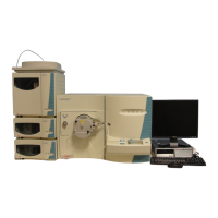
Do you have a question about the Thermo Finnigan LCQ Deca XP Plus and is the answer not in the manual?
| Brand | Thermo Finnigan |
|---|---|
| Model | LCQ Deca XP Plus |
| Category | Laboratory Equipment |
| Language | English |
Details the atmospheric pressure ionization source, its function, and types of probes (ESI, APCI, NSI).
Explains the quadrupole, octapole, and interoctapole lens system that transmits ions.
Describes the mass analyzer's role in ion storage, isolation, and analysis.
Explains the off-axis ion detection system with conversion dynode and electron multiplier.
Step-by-step procedure for safely removing the APCI probe assembly from the instrument.
Step-by-step procedure for correctly installing the ESI probe assembly.
Step-by-step procedure for safely removing the ESI probe assembly from the instrument.
Step-by-step procedure for correctly installing the APCI probe assembly.
Instructions for immediate system shutdown in emergency situations for safety.
Procedure to place the system in standby mode for short-term inactivity.
Procedure for completely powering down the system for extended periods or maintenance.
Step-by-step guide to properly start up the system after it has been shut down.
Procedure for resetting the MS detector when communication is lost.
Guidance on restoring default tune and calibration parameters for optimal performance.
Methods for selectively turning off MS detector components for troubleshooting or diagnostics.
Lists necessary tools, equipment, and chemicals for performing user maintenance.
Guidelines on the frequency of cleaning MS detector components based on usage.
Details routine maintenance procedures for the API source to ensure optimal performance.
Procedure for flushing the sample transfer line, tube, and probe with a cleaning solution.
Procedure for cleaning the spray shield, ion sweep cone, spray cone, and transfer capillary.
Steps to clear a blockage in the ion transfer capillary using a hypodermic tube.
Maintenance procedures for the APCI probe, including sample tube replacement.
Maintenance procedures for the ESI probe, including sample tube and needle seal replacement.
Procedures for cleaning and replacing components of the API stack.
Lists tools, equipment, and chemicals required for service maintenance procedures.
Guidelines on the frequency of cleaning MS detector components by service personnel.
Detailed procedures for cleaning the ion optics and mass analyzer components.
Steps for replacing the electron multiplier assembly or its anode and cathode.
How to run and interpret system diagnostics to identify electronic circuit issues.
Procedure for identifying and replacing fuses on various PCBs within the detector.
Overview of procedures for replacing various PCBs and assemblies in the instrument.
Procedures for replacing PCBs and power supply assemblies in the tower.
Steps to replace printed circuit boards within the embedded computer.
Procedures for replacing the Vent Delay PCB, backup battery, ion gauge, and vent valve.
Detailed procedures for replacing these major component boards and power supplies.
Steps for replacing the System Control PCB.
Procedure to replace the RF Voltage Control PCB and its housing unit.
Steps for replacing the turbomolecular pump.
Procedure for purging and decontaminating the rotary-vane pump oil.
Lists replaceable parts for the MS detector, categorized by component type.
Lists specific replaceable parts for the ESI probe assembly.
Lists specific replaceable parts for the APCI probe assembly.
Lists specific replaceable parts for the API stack components.
Lists specific replaceable parts for the ion optics system.
Lists specific replaceable parts for the mass analyzer.
Lists specific replaceable parts for the ion detection system.
Lists specific replaceable parts for the top cover plate of the vacuum manifold.
Lists specific replaceable parts for the divert/inject valve.
Lists specific replaceable parts for the syringe pump.
Lists specific replaceable parts for the turbomolecular pump.
Lists specific replaceable parts for the rotary-vane pumps.
Lists specific replaceable parts for vacuum system assemblies.
Lists specific replaceable parts for mechanical assemblies.
Lists specific replaceable parts for electrical assemblies.
Lists specific replaceable printed circuit boards (PCBs).
Lists specific replaceable parts for RF control/detection assemblies.
Lists specific replaceable cables.
Lists specific replaceable covers.
Lists replaceable parts for the data system hardware.
Lists items included in the chemicals kit.
Lists items included in the accessory kit.
Lists recommended spare parts for the system.
Lists accessories for the divert/inject valve.
Lists optional tools for system maintenance.
Flowchart illustrating the power-up diagnostic process for the instrument.
Table detailing pump and service diagnostics, normal conditions, and failure corrections.
Table outlining initialization and download diagnostics steps and expected results.
Table detailing data system diagnostic tests and failure indications.
Detailed diagnostic parameters, readback numbers, and signal/repair paths.