Do you have a question about the Thermo Scientific Maxi Mix II and is the answer not in the manual?
Declares product conformity with technical requirements and standards for EMC and Safety.
Specifies operating and storage conditions including temperature, humidity, and altitude limits.
Explains warning, caution, and note symbols used to indicate potential hazards or important information.
Emphasizes reading the manual, following instructions, and adhering to local electrical codes for safe operation.
Details safety precautions related to electrical shock and personal injury, including using grounded outlets and avoiding flammable materials.
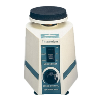
Defines the purpose of the vortex mixer for general laboratory applications, vortexing tubes, and vessels up to 125 ml.
Explains how the mixer operates using a lubricated motor, power switch modes (continuous, touch), and speed control via a rheostat.
Instructions for unpacking the Maxi-Mix II, noting included accessories like a rubber cup and replacement disc.
Guidance on placing the mixer on a sturdy, flat surface for optimal operation and stability.
Directs users to the specification plate for electrical details and advises contacting customer service for discrepancies.
Describes the function of the ON/OFF and mode switch, enabling continuous or touch operation for the mixing head.
Explains the nonlinear speed control mechanism and how to adjust speed and initiate vortex action.
Step-by-step instructions for replacing the power switch, including safety precautions.
Detailed procedure for replacing the speed control rheostat, involving disassembly and reassembly.
Instructions for replacing the microswitch, including desoldering, removing, and installing the new component.
Step-by-step guide for replacing the motor, covering disassembly, desoldering, and reassembly.
Procedure for replacing the damper springs, involving removal of housing and components.
Instructions for replacing the mixing surface disc, including cleaning the bonding area.
Steps for installing the single cup mixing head, involving securing the rubber cup and head.
Provides guidance on diagnosing and resolving common operational issues with the mixer.
Details the process for ordering replacement parts, including contact information and RMA requirements.
Illustrates the physical arrangement and part numbers of the mixer's components.
Details the warranty period, coverage limitations, and conditions for repair or replacement.
| Brand | Thermo Scientific |
|---|---|
| Model | Maxi Mix II |
| Category | Mixer |
| Language | English |