Disassembly and Replacement
NOTE: The lens does not have an orientation. It fits into a slight ridge, which positions it, and is
clamped in place by two washers, which are secured by screws on either side of the lens.
Replacement
1. Replace the lens.
CAUTION: NEVER TOUCH THE LENS WITH YOUR FINGERS. ALWAYS USE AN
UNCOATED LENS TISSUE OR SOFT COTTON CLOTH TO AVOID OILS
GETTING ONTO THE LENS. NEVER USE LENS PAPER WITH SILICONE
ADDITIVES.
2. Hold the lens with a lens tissue, soft cloth, or lab gloves and position the lens on the ridge in the
base.
3. Insert the screws through the washers and gently snug them up against the lens to hold it in place.
DO NOT OVERTIGHTEN OR THE LENS MAY BREAK!
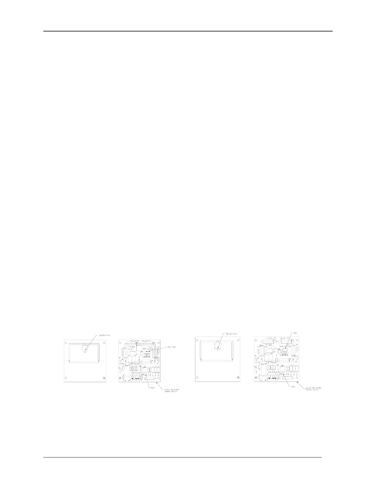
4. Replace the Sample Detector Circuit board (335901-6034 [UV] or 335901-6044 [Vis]).
NOTE: The detectors are specific to the instrument type (UV vs. Vis) so you cannot interchange
the two UV Detector boards and the Vis Detector boards by simply changing the jumper.
Ensure that you have the correct board and the correct jumper configuration:
W1 Jumper Settings:
Vis Sample Detector = pins 2 and 3 are jumpered
UV Sample Detector = pins 1 and 2 are jumpered and pins 3 and 4 are jumpered
UV Reference Detector = pins 1 and 2 are jumpered and pins 3 and 4 are jumpered
W2 Jumper Settings:
Sample Detector (Vis and UV) = W2 pins are jumpered together
Reference Detector (Vis and UV) = W2 pins are not jumpered
Figure 5.12 UV Detector board
Figure 5.13 Vis Detector board
5. Insert the ribbon cable into its connector making sure the No. 1 wire on the cable is at the No. 1
position on the connector and lock the connector.
5-12
 Loading...


