Do you have a question about the Thermopatch NL-15 R/SQR MAMMOTH and is the answer not in the manual?
| Brand | Thermopatch |
|---|---|
| Model | NL-15 R/SQR MAMMOTH |
| Category | Power Tool |
| Language | English |
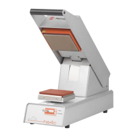
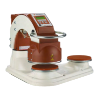
Details of the items included with the NL-15 R / SQR heat seal machine upon delivery.
Information regarding Thermopatch's warranty and product liability conditions.
Comprehensive list of technical parameters for the machine models.
Details on built-in safety features to protect the operator and machine.
Explanation of warning symbols used on the machine for enhanced safety.
Guidelines for moving the machine using its original packaging.
Instructions for storing the machine in optimal conditions.
Instructions for connecting and starting the NL-15 R / SQR machine.
How to activate and use the automatic mode for the press cycle.
Description of the safety frame and its function in interrupting the sealing cycle.
Overview of the control panel, its keys, and symbols on the display.
Instructions on how to adjust various machine settings like temperature, pressure, and time.
Details on how to change the operating temperature and its tolerance.
Procedure for checking machine temperature using indication labels.
Information on setting and adjusting the working pressure within safe limits.
How to adjust the sealing time settings for the machine.
Instructions for activating and setting the power save mode.
How to set different sealing times for left and right pads.
How to activate a second sealing cycle and when it can be switched off.
Various methods to interrupt the machine's sealing cycle.
Explanation of messages and failure codes displayed on the machine.
List of error codes and recommendation to contact supplier.
Details of 5 preprogrammed settings for different application types.
Requirements for air supply and connection of the machine.
Steps for unpacking and placing the machine on a work table.
Details on connecting the machine to the electricity grid and fuse information.
Daily cleaning procedures for the machine's exterior and press surfaces.
Periodic cleaning of pads, plates, and potential replacement of Teflon.
List of parts that require regular replacement for ongoing maintenance.
Component list for drawing 01, detailing parts and their codes.
Exploded view diagram illustrating components referenced in Parts list 01.
Component list for drawing 02, detailing parts and their codes.
Exploded view diagram illustrating components referenced in Parts list 02.
Component list for the NL-15 R model, referenced in drawing 03.
Exploded view diagram for the NL-15 R, corresponding to Parts list 03.
Component list for the NL-15 SQR model, referenced in drawing 03.
Exploded view diagram for the NL-15 SQR, corresponding to Parts list 03.
Diagram showing the safety frame upgrade modification for NL-15 models.
Component list for drawing 04, detailing electronic and other parts.
Exploded view diagram illustrating electronic and component parts for drawing 04.
Component list for drawing 05, detailing covers and structural parts.
Exploded view diagram illustrating safety covers and related components for drawing 05.
Component list for pneumatic parts, detailing hoses, valves, and sensors.
Pneumatic diagram showing component layout and part references.
Electrical wiring diagram for the Mammoth machine, showing connections and components.