STP321 / STP322 Programmable Thermostat Instruction Manual
E: sales@thermosense.co.uk
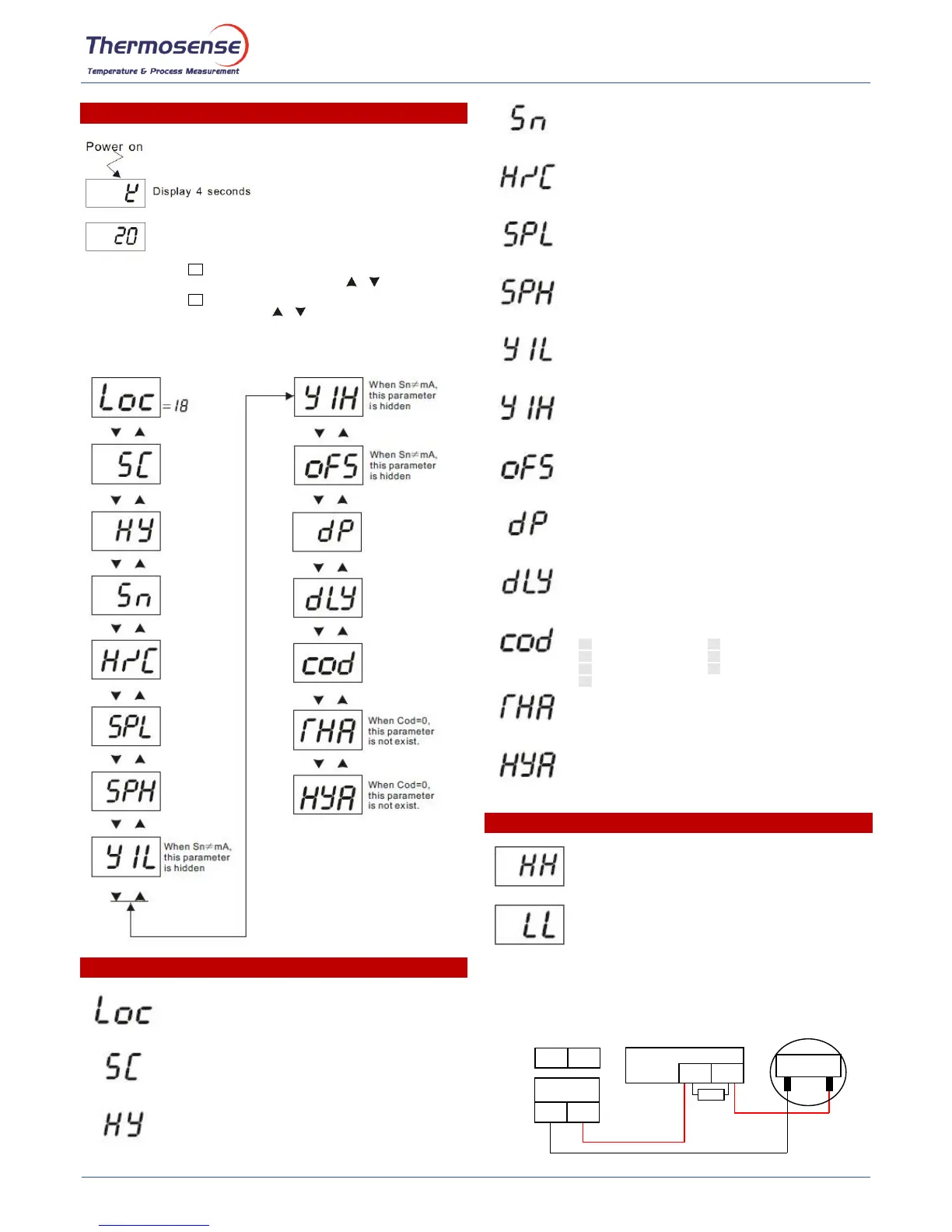
Operation
Press the function key for 3 seconds to enter the set point setting mode.
Then you can adjust the value with the up and down keys .
Press the function key for 6 seconds, then the window will display the following
parameters. Press the up and down keys to choose the parameters.
Note: Only when "Loc"=18 are all parameters programmable. When exiting the
program mode or after 10 sec of no key changes, “Loc” will default to “00”
Parameters Description
Lock parameter. The first parameter in the list.
The default value is 0.
To set following parameters, please set ”Loc”=18.
Compensation of the measuring value.
User can set this parameter when there is a difference between
measuring value and the real temperature.
Range: -19.9 to 20 degrees. Default: 0
Dead band of the control output.
For example: HY=5; SV=100; then the controller will start heating
when the SV=95; and stop heating when SV=105.
Range: 1-50 degrees. Default. 1
Input signal selection.
Press up or down key to choose the corresponding input sensor.
Range: K; J; Pt; mA
Default: K
Heating and cooling control action selection.
Press up or down key to choose the control action.
Range: heating H and cooling C
Default: H
Measurement low range
Range: -99 to 999°C
Default: 0
Measurement high range
Range: -99 to 999°C
Default: 900
Display value
When the input signal is mA, Y1L is the value for 4mA or 0mA.
When Sn ≠ mA, this parameter is hidden
When the input signal is mA, Y1H is the value for 20mA.
When Sn ≠ mA, this parameter is hidden
Selection of mA input range
YES = 4-20mA, NO = 0-20mA
When Sn ≠ mA, this parameter is hidden
Default: YES
Decimal point
dp=0, decimal point is inactive.
dp=1, decimal point is active.
Default: 0
Delaytime of main control output
Unit: Second
OUT indicating lamp should be light when the device is in delay time.
Default: 0
Deviation high and low alarm
Dead band of Alarm
Note: When alarm code is
C (Deviation high and low alarm) and D (Band alarm), this parameter
does not exist.
This code will be displayed when the temperature is higher than the
high limit of input sensor.
This code will be displayed when the input sensor crashed or the
temperature is lower than the low limit of input sensor.
4-20mA Transmitter
Source
External Power Supply
240Vac Input
Typical wiring layout for 4-20mA input signal with external
loop power supply and mA transmitter as source
 Loading...