RST
SET
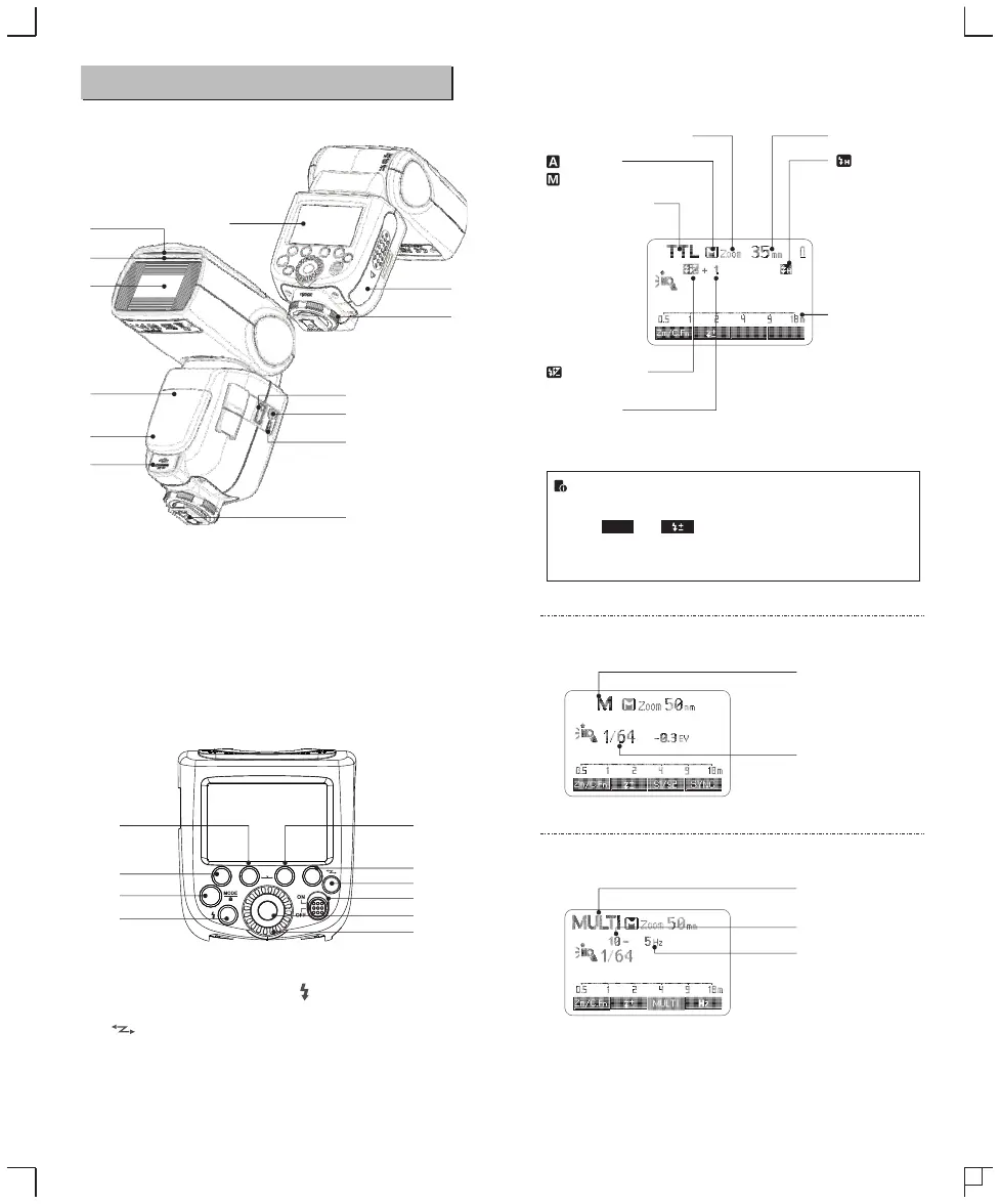
01. Catchlight Panel
02. Built-in Wide Panel
03. Flash Head
04. Optic Control Sensor
05. Wireless Control Port
06. Sync Cord Jack
07. Hotshoe
08. Dot-marix LCD Panel
09. Lock Ring
10. Battery Compartment
11. USB Port
12. Slave Flash Ready Indicator
13. External Power Supply Socket
● Body
14. <MODE> Mode Selection
Button / Lock button
15. < >Wireless Selection
Button
16. Select Dial
17. <SET> Set Button
18. ON/OFF Power Switch
19. < > Test Button / Flash
Ready Indicator
20. Function Button 1
21. Function Button 2
22. Function Button 3
23. Function Button 4
● Control Panel
● LCD Panel
Name of Parts
20
21
22
14
19
17
18
15
23
16
(1) TTL Autoflash
Zoom : zoom display (Page 44)
: Automatic
: Manual(Page 35)
TTL : TTL autoflash
Focus length (Page 44)
: High-speed sync
(Page 34)
: Flash exposure
compensation (Page 33)
Distance indicator
display
Flash exposure
compensation amount
(2) M Manual Flash
●The display will only show the settings currently applied.
● The functions displayed above function buttons 1 to 4, such
as and , change according to settings’ status.
● When a button or dial is operated, the LCD panel
illuminated.
M : Manual flash
Manual flash output
(3) Multi Stroboscopic Flash
Multi : Stroboscopic flash
Number of flashes
Flash frequency
08
05
06
11
07
09
10
12
04
03
02
01
13
SYNC
- 29 - - 30 -
 Loading...