4
LEVEL: Variable over ±4 divisions. Press ZERO/(VAR)
key to set zero level triggering, press again to
return to variable.
SLOPE: Can be POS (positive edge triggered) or NEG
(negative edge triggered).
COUPL: Can be AC, DC or HFREJ (high frequency
reject). With TV and video signals, use AC for Line
sync and HFREJ for Frame sync.
N.B. The lamp marked TRIG, to the right of the SINGLE key,
indicates the presence of a trigger signal.
Other functions are specific to the digital storage function:
RUN/HOLD: RUN — enables continuous digitising with
synchronism defined by the trigger mode control.
The previous contents of both digitising memories
are overwritten unless one has already been frozen
using the channel ON/OFF key.
HOLD — disables digitising. The contents of both
digitising memories are frozen.
SINGLE: Only operates when RUN/HOLD is set to
HOLD. Enables a single update of the digitising
memory with synchronism defined by the trigger
mode control.
EVENTS Sets a number of trigger events (0 to 15) which
DELAY: must occur before a trigger is sent to the digitiser.
This allows delayed triggering on complex single-event
waveforms, and can be used to avoid mis-triggering of complex
repetitive waveforms (similarly to Sweep Hold-off on a real-time
oscilloscope). Pressing either key shows the existing value on the
display for three seconds. Repeated pressing increments or
decrements the number, the keys auto-repeat if held. To rapidly
turn events delay off (i.e. to 00) press both keys simultaneously.
Note that when using AUTO trigger mode, events
delay will increase the minimum frequency at
which it can be used from 20Hz to (1 + 20Hz,
where n is the number of events.
TIME DELAY: Sets the time delay between the trigger event and
the start of the digitising process. The delay is
measured in screen divisions and can be positive
(POST TRIGGER DELAY) or negative (PRE
TRIGGER DELAY).
POST — this acts similarly to sweep delay on a
real-time oscilloscope. By adding time delay and
then selecting a faster timebase speed, a section of
a waveform occurring long after the trigger event
can be examined. For "normal" mode timebase
speeds (100msec/div to 5usec/div) the number of
divisions of post-trigger delay is automatically
increased or decreased to maintain a constant time
delay when the timebase speed is changed (within
a limit of 9,999 divisions maximum).
PRE — there is no equivalent to pre-trigger on a
real-time oscilloscope. Pre-trigger allows the part of
the waveform which occurred before the trigger to
be stored and observed. The maximum pre-trigger
delay is —40 divisions.
Pressing either key shows the existing value of
delay on the screen for three seconds. Repeated
pressing increments or decrements the number,
the keys autorepeat if held. To rapidly turn time
delay off (i.e. to 0000) press both keys
simultaneously.
N.B. Neither pre nor post trigger delay is available
in "repeat" mode. In "roll" mode only post trigger
delay is available. See Section R14. Roll Mode
Operation for an explanation.
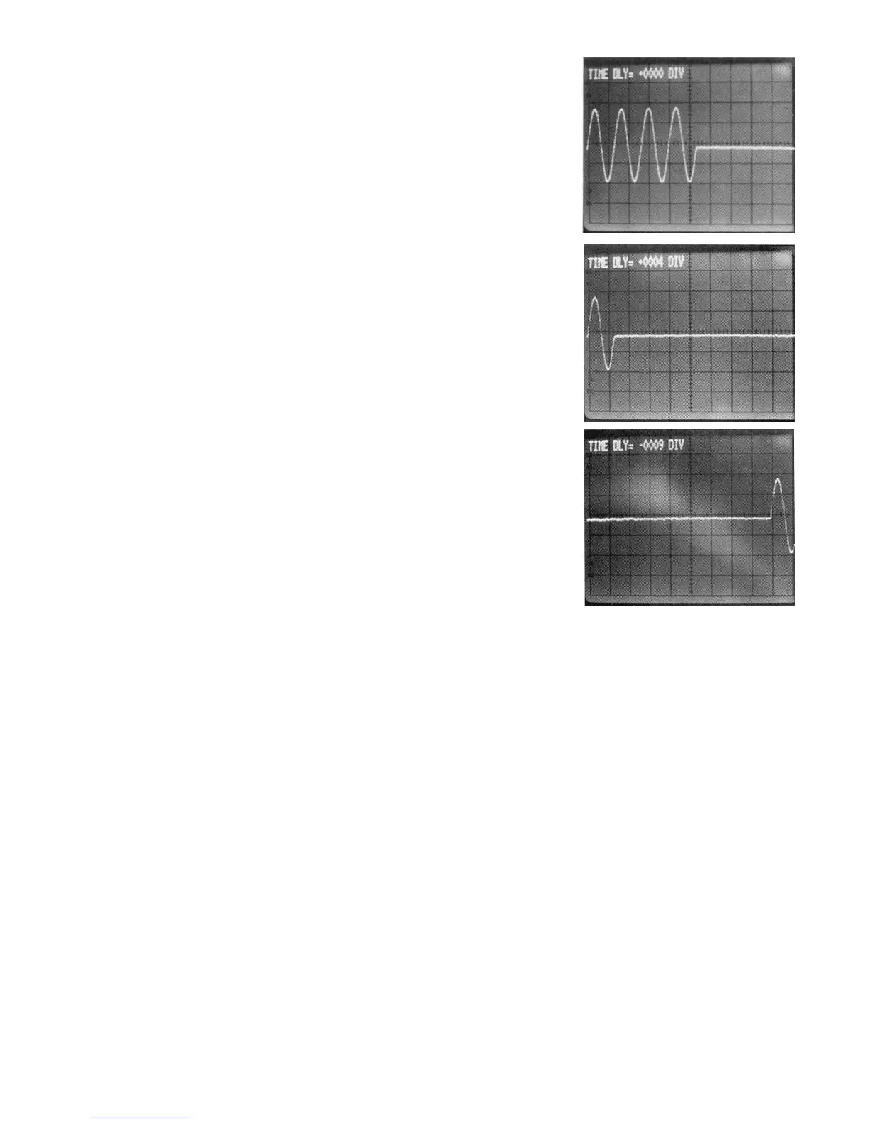
A waveform burst (4
cycles) captured with
no trigger time delay.
The same waveform
burst captured with 4
divisions of post
trigger delay.
The same waveform
burst captured with 9
divisions of pre
trigger delay.
R10. TRACE A AND TRACE B
The DSA524 can display two traces simultaneously, the traces
are called A and B. Each trace has its own 1K word memory
which can be loaded with data either from the corresponding
digitising memory (CH1 for trace A or CH2 for trace B) or from
an indexed waveform memory.
The trace controls operate on the waveform after it has been
digitised but before it has been 'displayed. Therefore they can
be used to modify waveforms recalled from a waveform store
as well as waveforms taken from the digitising memories of the
input channels.
POSITION: Enables the vertical position of the trace on the
display to be adjusted. Pressing the HOME/(VAR)
key toggles between fixed position (HOME) and
variable position.
GAIN Enable intermediate sensitivity levels to be set.
VARIABLE: Pressing the CAL/( UNCAL) key toggles
between calibrated gain (X1) and variable gain
(X1 to X0.2).
CH1 Pressing this key causes the trace to display the
(or
CH2): contents of the digitising memory for the
corresponding input channel.
RCL(NN): (Recall indexed waveform memory). Pressing
this key followed by a two digit number on the keypad
causes the trace to display the contents of the
corresponding waveform memory. It also sets RUN
/HOLD to HOLD.
OFF: Pressing the CH1 (or CH2) and RCL(NN) keys
simultaneously turns the trace off (the CH key should be
pressed first, otherwise RUN/HOLD will be set to HOLD).
 Loading...