9
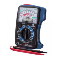
1. Needle display
2. Adjustment screw to 0
3. Potentiometer for the
ohmmeter function
4. Function switch
5. Test leads
• Function switch : OFF, V DCV (DC Voltmeter), V~ ACV (AC Voltmeter),
mA DCA (DC Ammeter), BAT (battery test), Ω (Ohmmeter).
• Selector switch : turn the switch to select the appropriate function and range.
• Needle : will indicate the measured value.
• Before starting, check that the needle is set to 0. If it isn’t, adjust its position
by turning the adjusting screw.
During the measurement:
- If the needle stays to the left on position 0, this means that the position of the
test plungers is incorrect; reverse the position and test again.
- if the needle stays to the right on position 300 (or 60 or 12), this means that
the measured value is higher than the maximum value of the selected range.
You must remove the test plungers from the circuit. Then select a suitable
rating and test again.
Always start with the highest rating if you are in doubt about the value to be
measured.
1kΩ
I
I
I
I
I
I
I
I
I
I
I
I
I
I
I
I
I
I
I
I
I
I
I
I
I
I
I
I
I
I
I
I
I
I
I
I
I
I
I
I
I
I
I
I
I
I
I
I
I
I
I
I
I
I
I
I
I
I
I
I
I
I
I
I
I
I
I
I
I
I
I
I
I
I
I
I
I
I
I
I
I
I
I
I
I
I
I
I
I
I
I
I
I
I
I
I
I
I
I
I
I
I
I
I
I
I
I
I
I
I
I
I
I
I
I
I
I
I
I
I
I
I
I
I
I
I
500
100
50
20
10
OHMS
OL
OL
BATT
dB
OL
V
5
2
1
0
V.mA
2kΩ/V
OL
OdB: 1mW 600Ω
0
0
0
50
10
2
100
20
4
150
30
6
200
40
8
250
50
10
300
60
12
~
~
I
I
I
I
I
I
I
I
I
I
I
I
I
I
I
I
I
I
I
I
I
I
I
I
I
I
I
I
I
I
I
I
I
I
I
I
I
I
I
I
I
I
I
I
I
I
I
I
I
I
I
I
I
I
I
I
I
I
I
I
I
I
I
I
I
I
I
BAD
GOOD
?
+ 4
20
30
35 36 37
I
I
I
I
I
I
I
I
I
I
I
I
I
I
I
I
1kΩ
I
I
I
I
I
I
I
I
I
I
I
I
I
I
I
I
I
I
I
I
I
I
I
I
I
I
I
I
I
I
I
I
I
I
I
I
I
I
I
I
I
I
I
I
I
I
I
I
I
I
I
I
I
I
I
I
I
I
I
I
I
I
I
I
I
I
I
I
I
I
I
I
I
I
I
I
I
I
I
I
I
I
I
I
I
I
I
I
I
I
I
I
I
I
I
I
I
I
I
I
I
I
I
I
I
I
I
I
I
I
I
I
I
I
I
I
I
I
I
I
I
I
I
I
I
I
500
100
50
20
10
OHMS
OL
OL
BATT
dB
OL
V
5
2
1
0
V.mA
2kΩ/V
OL
OdB: 1mW 600Ω
0
0
0
50
10
2
100
20
4
150
30
6
200
40
8
250
50
10
300
60
12
~
~
I
I
I
I
I
I
I
I
I
I
I
I
I
I
I
I
I
I
I
I
I
I
I
I
I
I
I
I
I
I
I
I
I
I
I
I
I
I
I
I
I
I
I
I
I
I
I
I
I
I
I
I
I
I
I
I
I
I
I
I
I
I
I
I
I
I
I
BAD
GOOD
?
+4
20
30
35 36 37
0Ω ADJ.
I
I
I
I
I
I
I
I
I
I
I
I
I
I
I
I
PROTECTION
FUSE & DIODE
B
A
T.
mA
V~
V
9V
X10
X1k
1,5V
30
600
60
120
300
300
120
120
120
60
12
OFF
+
-
CAT III
!
300V max
600mA 300V max FUSED
~
Ω
1
2
3
4
5
 Loading...