4
shown. Please refer to the table in Figure 1 for the
equivalent Data / Accessory Port signals.
____ PTT
____ Mic Input
____ Speaker Audio
____ Accessory Voltage
____ Mic Ground**
____ PTT Ground**
____ Chassis Ground**
** Note that some radios only have one ground pin.
** Speaker and Accy Power are not always available.
· Verify Pin-out – This step is Extremely Important
since not all manufacturers use the same numbering
convention for their connectors. This is especially true
of radios using RJ-45 mic connectors. This brief
verification process could ward off a major disaster
when you turn on the power! This procedure verifies
that the pin numbers, which you just identified in the
Operators Manual, do in fact match the numbers
identified on the Programming Socket. The easiest way
to do this is to use a multimeter to verify some of the
more important lines. Before you start, you will need to
make sure that the radio power is OFF, that there are
NO JUMPERS are installed in JP-1, and that the
supplied cable is connected between the SignaLink and
the radio.
Note that you should not find the lines “scrambled”.
They will either be in the correct order or they will be
completely reversed (pin 1=8, 2=7, 3=6, etc).
First check the Ground pin (or pins) recorded earlier.
You can do this by checking for continuity between the
radio chassis and the pins numbered on the
Programming Socket (JP-1). JP-1 is a very convenient
place to probe since it is wired 1:1 to every pin on the
radio connector. You will be checking against the
numbers you recorded earlier from the Operators
Manual. Note that if your radio has a separate mic
ground it may have a slight resistance to chassis
ground. Any other ground pin should test very close to
zero ohms. If you do not get the expected continuity in
this test, try checking against the numbers in the
reverse order (1=8, 2=7, 3=6, etc). It would probably
be very helpful to make a new table using the reversed
number sequence to avoid mistakes! This step should
establish whether or not the radio connector is “reverse
ordered” and allow you to correct the numbers on your
table.
Once you are confident about the ground lines you can
move on to other pins. If your radio had Accessory
Power you should be able to turn ON the radio and use
your multimeter (volts scale) to test for power on the
appropriate pin of JP-1.
You can test the PTT pin as follows: First check the
pin with your multimeter (volts). You should see a
voltage on the PTT pin (5-12v) when the radio is ON.
You should be able to key the radio by grounding the
PTT line. For the sake of safety, you should ground the
PTT pin through a small value resistor (100-1000
ohms) in case it’s not the pin you think it is! Be sure
your radio power is set to LOW and an antenna or
dummy load is connected for this test, as the radio will
go into “transmit” with the line grounded.
If the Speaker signal is available on the connector you
are using, then you can try attaching a speaker or
headphone to the appropriate pin on JP-1 to see if you
can hear audio. Note that you will NOT be able to hear
anything if the speaker source is a low level output
(usually the case on Data and Accessory ports).
There is no easy way to test the mic line but there will
be little doubt about it if the other lines are correct.
The main thing you are looking for here is to determine
whether or not the connector numbers are reversed on
your radio. If you have any unresolved errors, then you
should double check your numbering in the Operators
Manual again.
SPKR
MIC
PTT
PWR
G
- - -
8_______________________
7_______________________
6_______________________
5_______________________
4_______________________
3_______________________
2_______________________
1_______________________
JP1
G
G
Radio Connector
SPKR
MIC
PTT
PWR
G
- - -
8_______________________
7_______________________
6_______________________
5_______________________
4_______________________
3_______________________
2_______________________
1_______________________
JP1
G
G
Radio Connector
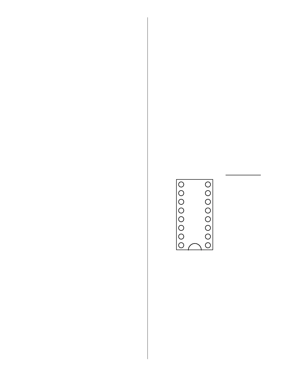
Figure 2 – Jumper Wiring Diagram
· Draw Jumper Wires - Once you have verified your
pin-out and are comfortable with the results, you are
ready to label the lines in Figure-2 and draw in the
jumper wires. To do this, you simply need to draw a
line between the pins on the left of JP-1 (G, PWR, PTT,
Mic & SPKR) and their appropriate match on the right
side of the diagram. For example, draw a line between
“PWR” pin on the left of JP-1 and the line that you
labeled “Accessory Voltage”. The “PTT” pin should be
connected to the pin that you labeled “PTT” and so on.
If you are installing the SignaLink on a Data or
Accessory port, then refer to Figure 1 for the correct
signal names. An example of the Jumper Wiring
Diagram for a Kenwood TS-450 is shown in Figure 3.
 Loading...