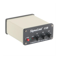
3
ground connections (Mic Ground & PTT Ground). The
Programming Socket has multiple ground (G) connections
for this reason.
On many radios the mic connector also provides access to
Supply Voltage and Speaker Audio. Supply Voltage has
already been discussed in the section on “Connecting
Power”. If your radio has power available on the mic
connector then you will be instructed to connect it later in
this section. If Speaker Audio is not available from the mic
connector on your radio then you will need to install a short
(2ft) jumper cable from the External Speaker or Headphone
jack on your radio to the SPKR jack on the rear panel of the
SignaLink. If this signal is available on the mic connector,
then you will connect it later in this section.
Before proceeding with jumper installation you should verify
in your radio manual that the radio PTT requirements do not
exceed the specifications of the SignaLink keying circuit.
Verify that the PTT is “Grounded” to make the radio
transmit and the PTT signal does not exceed 15 volts @
75ma. This is well within the ratings of all modern radios
but could be a problem on some older rigs. If your radio
exceeds these specifications or requires some other keying
arrangement, then you will need to key the radio using a low
voltage/low current relay.
Identifying Jumper Locations – This is a two-step process.
First we will identify the mic connector pin-out and then we
will verify that they are correct. The verification process is
very important since incorrect wiring could damage your
equipment. The final steps will be to draw a wiring diagram
using Figure-1 and actually install the jumpers.
• Lookup Mic Pin-out – In your radio’s Operator
Manual, find the page that identifies the pin-out of the
microphone connector. Using the manual, identify the
pin numbers assigned to the following signals and
record them below:
____ PTT (Sometimes called “Standby”)
____ Mic Input
____ Speaker Audio
____ Accessory Power
____ Mic Ground
____ PTT or Chassis Ground
** Note that some radios only have one ground pin.
** Speaker and Accy. Power are not always available.
• Verify Pin-out – This step is Extremely Important
since not all manufacturers use the same numbering
convention for their connectors. This is especially true
of radios using RJ-45 mic connectors. This brief
verification process could ward off a major disaster
when you turn on the power! This procedure verifies
that the pin numbers which you just identified in the
Operators Manual do in fact match the numbers
identified on the Programming Socket. The easiest way
to do this is to use a multimeter to verify some of the
more important lines. Before you start, you will need to
make sure the radio power is OFF, make sure NO
JUMPERS are installed in JP-1, and the supplied cable
is connected between the SignaLink and the radio.
Note that you should not find the lines “scrambled”.
They will either be in the correct order or they will be
completely reversed (pin 1=8, 2=7, 3=6, etc).
First check the Ground pin (or pins) recorded earlier.
You can do this by checking for continuity between the
radio chassis and the pins numbered on the
Programming Socket (JP-1). JP-1 is a very convenient
place to probe since it is wired 1:1 to every pin on the
radio connector. You will be checking against the
numbers you recorded earlier from the Operators
Manual. Note that if your radio has a separate mic
ground it may have a slight resistance to chassis ground.
Any other ground pin should test very close to zero
ohms. If you do not get the expected continuity in this
test, try checking against the numbers in the reverse
order (1=8, 2=7, 3=6, etc). It would probably be very
helpful to make a new table using the reversed number
sequence to avoid mistakes! This step should establish
whether or not the radio connector is “reverse ordered”
and allow you to correct the numbers on your table.
Once you are confident about the ground lines you can
move on to other pins. If your radio had Accessory
Power you should be able to turn ON the radio and use
your multimeter (volts scale) to test for power on the
appropriate pin of JP-1.
You can test the PTT pin as follows: First check the pin
with your multimeter (volts). You should see a voltage
on the PTT pin (5-12v) when the radio is ON. You
should be able to key the radio by grounding the PTT
line. For the sake of safety, you might want to ground
the PTT pin through a small value resistor (100-1000
ohms) in case it’s not the pin you think it is! Be sure
your radio power is set to LOW and an antenna or
dummy load is connected for this test, as the radio will
go into “transmit” with the line grounded.
If the Speaker signal is available on your mic connector,
you can try attaching a speaker or headphone to the
appropriate pin on JP-1 to see if you can hear audio.
There is no easy way to test the mic line but there will
be little doubt about it if the other lines are correct. The
main thing you are looking for here is to determine
whether or not the connector numbers are reversed on
your radio. If you have any unresolved errors you
should double check your numbering in the Operators
Manual again.
 Loading...